GP-PC200B BMS to Victron Inverter Connection Setup Guide
This manual describes how to connect and configure the Gobel Power GP-PC200B BMS battery system with a Victron inverter and Cerbo GX device.

Required Materials
Before starting, ensure you have the following equipment and materials ready:
| # | Material Name | Description |
|---|---|---|
| 1 | Battery pack using GP-PC200B BMS | Gobel Power battery system with built-in GP-PC200B BMS |
| 2 | Victron inverter and Cerbo GX device | Official Victron inverter and communication gateway |
| 3 | Victron official Type B BMS connection cable | VE.Can to CAN-bus BMS dedicated cable (Type B) |
The Victron Type B VE.Can to CAN-bus BMS cable is used for CAN-Bus communication between Gobel Power batteries and Victron GX devices. You can obtain this cable from the Victron official website.
Physical Connections
BMS Settings
Before connecting the battery to Victron devices, verify that the GP-PC200B BMS communication protocol is correctly configured. For detailed setup instructions, refer to the GP-PC200B BMS Communication Settings documentation.
GP-PC200B BMS Communication Settings documentation: https://docs.gobelpower.com/docs/bms/GP-PC200B/communication/
Inverter Connection
-
Use the Victron Type B VE.Can to CAN-bus BMS dedicated cable to establish CAN-Bus communication between the Gobel Power battery and the Victron GX device. This cable is available at the following link: https://www.victronenergy.com/cables/ve-can-to-can-bus-bms
-
Connect the BMS-CAN end of the Victron cable to the battery's CAN communication port.
-
Connect the Victron VE.CAN end of the cable to the Cerbo GX device's communication port:
- Older Cerbo GX: connect to the BMS-CAN port
- Newer Cerbo GX: connect to the VE.CAN port
Cerbo GX Setup
After completing the physical connections, follow the steps below to configure the Cerbo GX device.
1. BMS-CAN Port Configuration
Go to Settings -> Services -> BMS-Can Port -> CAN-bus profile and ensure CAN-bus BMS (500 kbit/s) is selected.
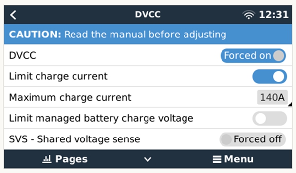
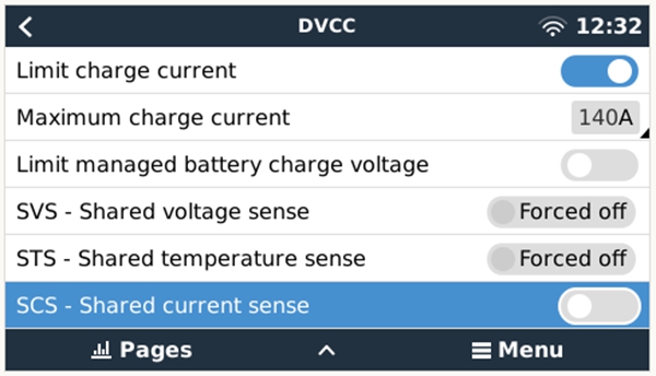
2. DVCC Settings
Go to Settings -> DVCC and configure the following parameters:
| Setting | Value |
|---|---|
| DVCC | Forced on |
| Limit charge current (optional) | ON |
| Max charge current | Number of battery packs x 0.5 x single pack capacity (Ah) |
Example: For 2 battery packs of 51.2V 280Ah, the maximum charge current is 2 x 0.5 x 280 = 280A.
Maximum charge current = Number of battery packs x 0.5 x single pack capacity (Ah). Please calculate based on the actual number and capacity of your battery packs.
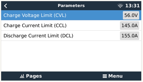
3. Device Identification Confirmation
After completing the above settings, the battery device will appear in the device list. You can view real-time battery data on the Battery Parameters page.
VictronConnect App Setup
Use the VictronConnect mobile application to configure your Victron devices.
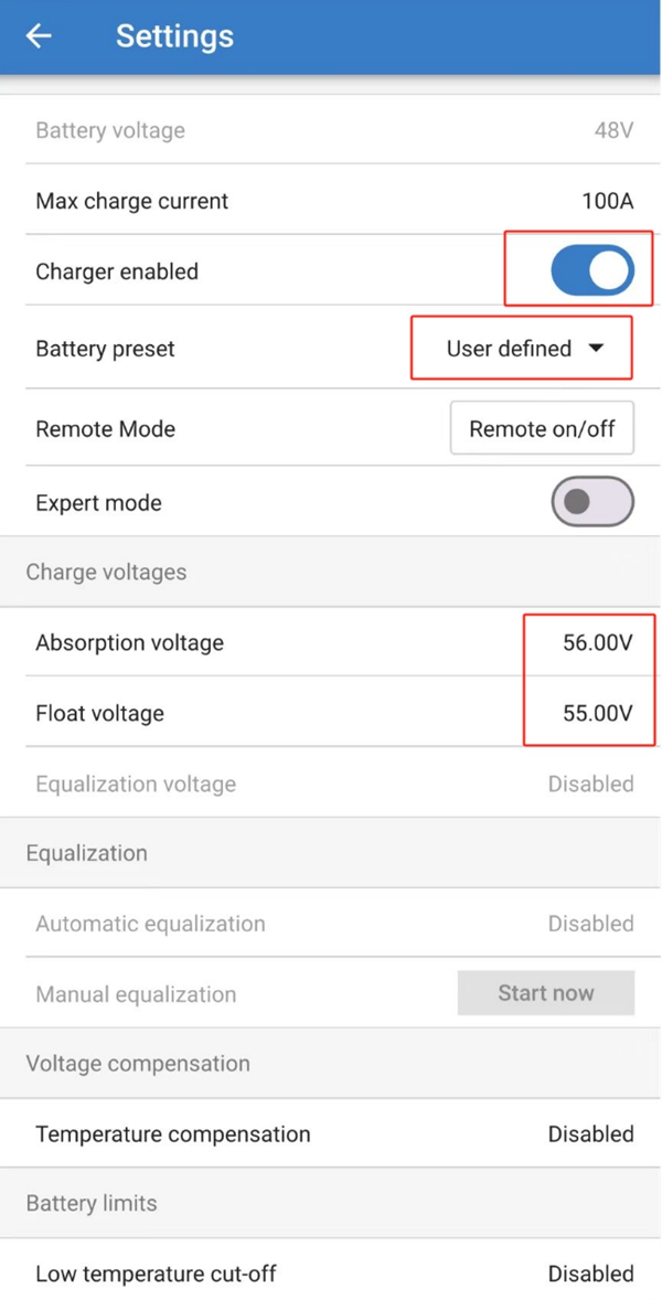
1. Victron MPPT Solar Charge Controller Settings
In the VictronConnect App, select the MPPT device and configure the following parameters:
| Setting | Value |
|---|---|
| Charger Enabled | ON |
| Battery preset | User defined |
| Absorption Voltage | Equal to Charge Voltage Limit (CVL) |
| Float voltage | Slightly lower than Absorption Voltage |
| Low temperature cut-off | Disabled |
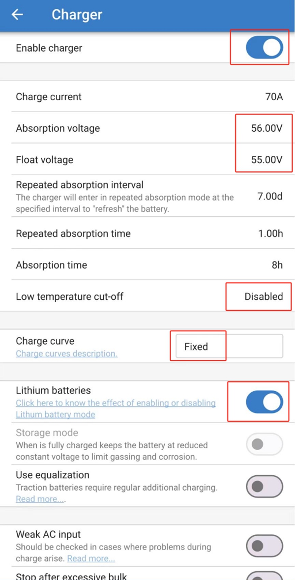
2. Victron Inverter/Charger Settings
In the VictronConnect App, select the inverter/charger device and configure the Charger settings with the following parameters:
| Setting | Value |
|---|---|
| Enable Charger | ON |
| Absorption Voltage | Equal to Charge Voltage Limit (CVL) |
| Float voltage | Slightly lower than Absorption Voltage |
| Low temperature cut-off | Disabled |
| Charge Curve | Fixed |
| Lithium batteries | ON |
VE Configuration Tools Setup
Use the Victron VE Configuration Tools software to perform advanced configuration of the inverter/charger.
1. Inverter/Charger Settings
Enable Charger
Check the Enable charger option to enable the charger function.
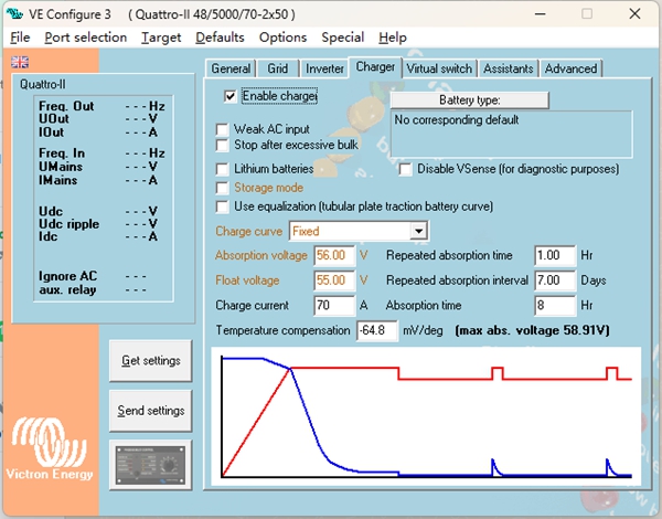
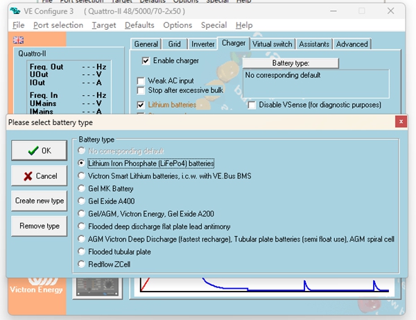
Lithium Batteries Mode
Check the Lithium batteries option to enable lithium battery mode.
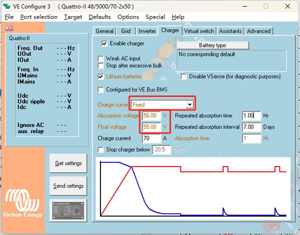
Other Settings
Configure the following parameters:
| Setting | Value |
|---|---|
| Charge curve | Fixed |
| Absorption voltage | Equal to Charge Voltage Limit (CVL) |
| Float voltage | Slightly lower than Absorption Voltage |
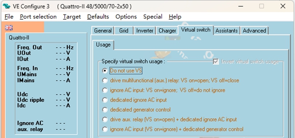
2. Virtual Switch Settings
In the Virtual switch tab, select Do not use VS.
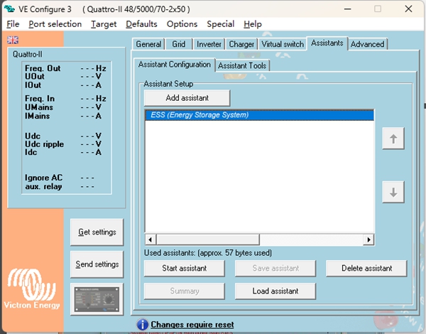
3. ESS (Energy Storage System) Assistant Setup -- Add Assistant
In the Assistant tab, click to add an assistant and select ESS (Energy Storage System).
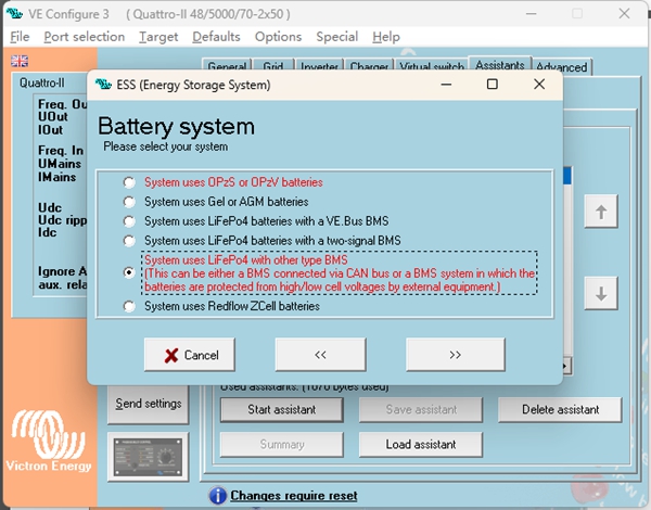
4. ESS Assistant Setup -- Configure Parameters
Select System Type
Click Start assistant and select option 5 from the choices.
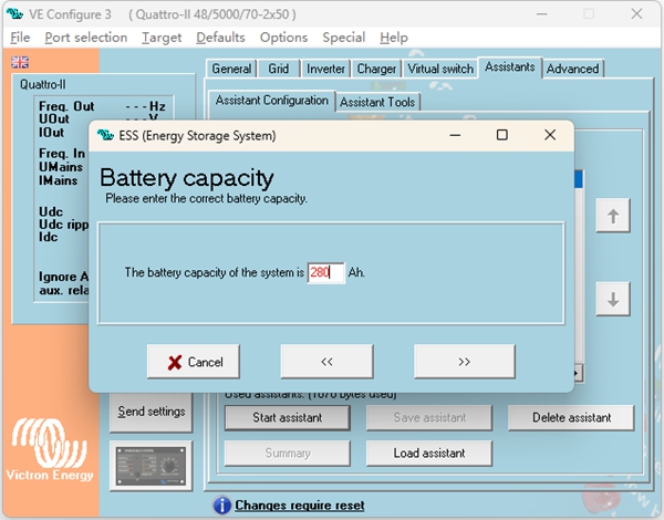
Set Total Capacity
Enter the total capacity of the battery system.
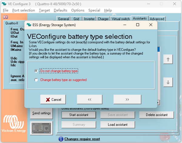
Battery Type
Select Do not change battery type.
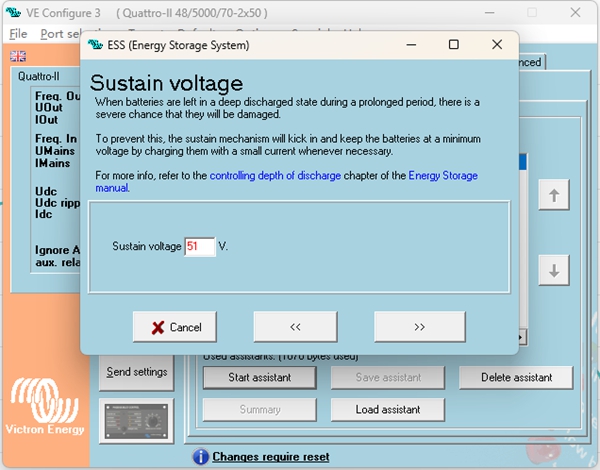
Set Sustain Voltage
Set the Sustain voltage to 51V.
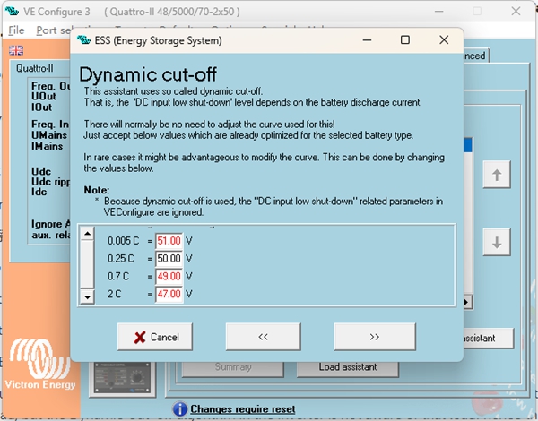
Set Dynamic Cut-off
Configure the dynamic cut-off voltages according to the following relationships:
| Discharge Rate | Cut-off Voltage |
|---|---|
| 0.005C | 49V |
| 0.25C | 48V |
| 0.7C | 48V |
| 2C | 47V |
Restart Offset
Use the default Restart offset value; no modification is needed.

After completing all the above configurations, the GP-PC200B BMS battery system will have successfully established communication and control connection with the Victron inverter. You can verify the battery status in the Cerbo GX device list.