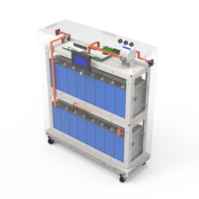
GP-Project-X Assembly Manual
| Item | Content |
|---|---|
| Brand | Gobel Power |
| Product Model | GP-Project-X |
| Manual Type | Assembly Manual |
| Applicable Product | LiFePO4 Low-Voltage Battery DIY Kit |
| Cell Specification | 314Ah LiFePO4 Lithium Iron Phosphate Cell, 1P16S in Series |
| BMS Specification | 200A, with 2A Active Balancing |
Safety Precautions
Before assembling the GP-Project-X battery kit, please read and observe the following safety precautions carefully.
- Power-off Operation: Ensure all external power sources are disconnected during assembly to avoid live operation.
- Electric Shock Prevention: After battery assembly is complete, high voltage exists between terminals (rated 51.2V). Always confirm the circuit breaker is disconnected before touching.
- Insulation Requirements: All conductive parts must be properly installed with insulating materials to avoid short circuits.
- Short Circuit Protection: When cells and busbars are exposed, strictly prohibit using metal tools to touch both positive and negative poles simultaneously to prevent sparks or high temperatures from short circuits.
- Temperature Requirements: Cells should be assembled in a room temperature environment (10°C ~ 35°C), avoiding high temperature or extremely cold environments.
- Polarity Confirmation: When connecting cells, be sure to repeatedly confirm the correct positive and negative pole directions. Reverse connection will cause serious damage.
- Cell Handling: Individual 314Ah cells are heavy. Use correct posture when handling, seek help if necessary, and avoid injury.
- Heavy Lifting: The battery module is heavy after assembly. Use casters when moving and ensure the ground is flat.
- Sharp Edge Protection: Metal frames, busbars, and terminals may have sharp edges. It is recommended to wear protective gloves during operation.
- Pinch Prevention: When adjusting the moving cell compression side plate, be careful not to get fingers caught between the side plate and the cell.
- Work Environment: Assemble in a dry, well-ventilated indoor environment, away from flammable materials and water sources.
- Keep Children Away: During assembly and testing, ensure children stay away from the work area.
- Qualified Tools: Use tools with insulated handles, and ensure tool specifications match the screws to avoid stripping.
- Personal Protection: It is recommended to wear insulated gloves and safety glasses during assembly operations.
Incorrect assembly may result in battery damage, fire, or personal injury. If you are uncertain about any step, please contact Gobel Power technical support.
Product Introduction
GP-Project-X is a LiFePO4 low-voltage (51.2V) battery DIY kit launched by Gobel Power, suitable for various 280Ah and 314Ah LiFePO4 cells. It adopts a modular design for simple and rapid installation.
Main Features
- Cell Specification: Uses 314Ah LiFePO4 lithium iron phosphate cells
- Connection Method: 1P16S in series
- BMS Protection: 200A BMS, with 2A active balancing
- Additional Protection: Equipped with additional circuit breaker and fuse protection
- Cell Layout: Cells placed upright
- Enclosure Option: Optional transparent flame-retardant plastic enclosure
Applicable Scenarios
GP-Project-X is suitable for home energy storage, off-grid solar systems, and other low-voltage large-capacity energy storage application scenarios.
Parts List
| No. | Name | Specification/Qty | Image |
|---|---|---|---|
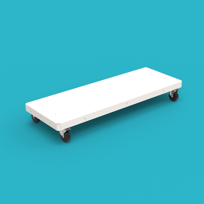
| 01 | Base | 1 pc |  |
| 02 | Metal Frame | 2 pcs | 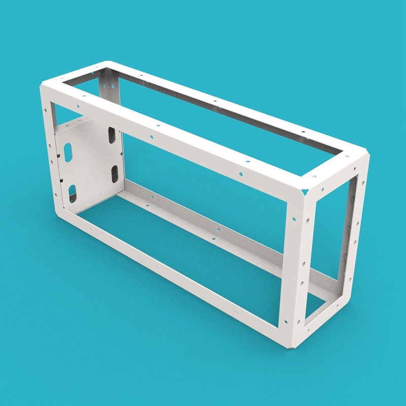 |
| 03 | Enclosure Back Panel | 1 pc | 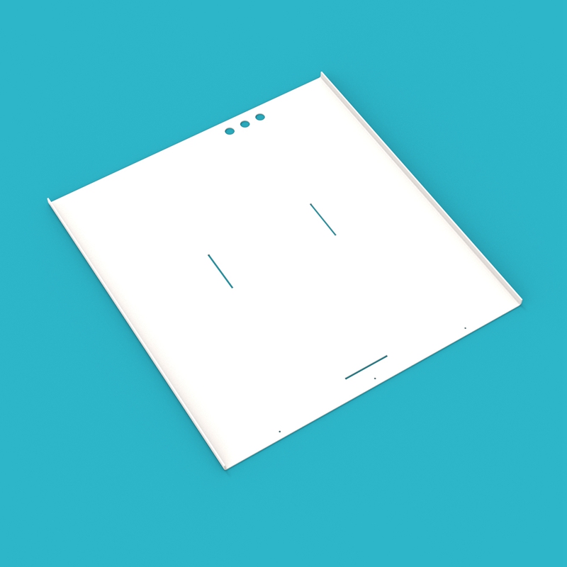 |
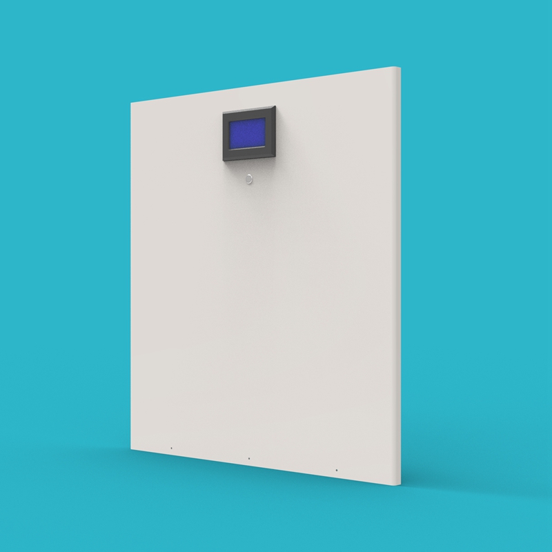
| 04 | Enclosure Front Panel | 1 pc |  |
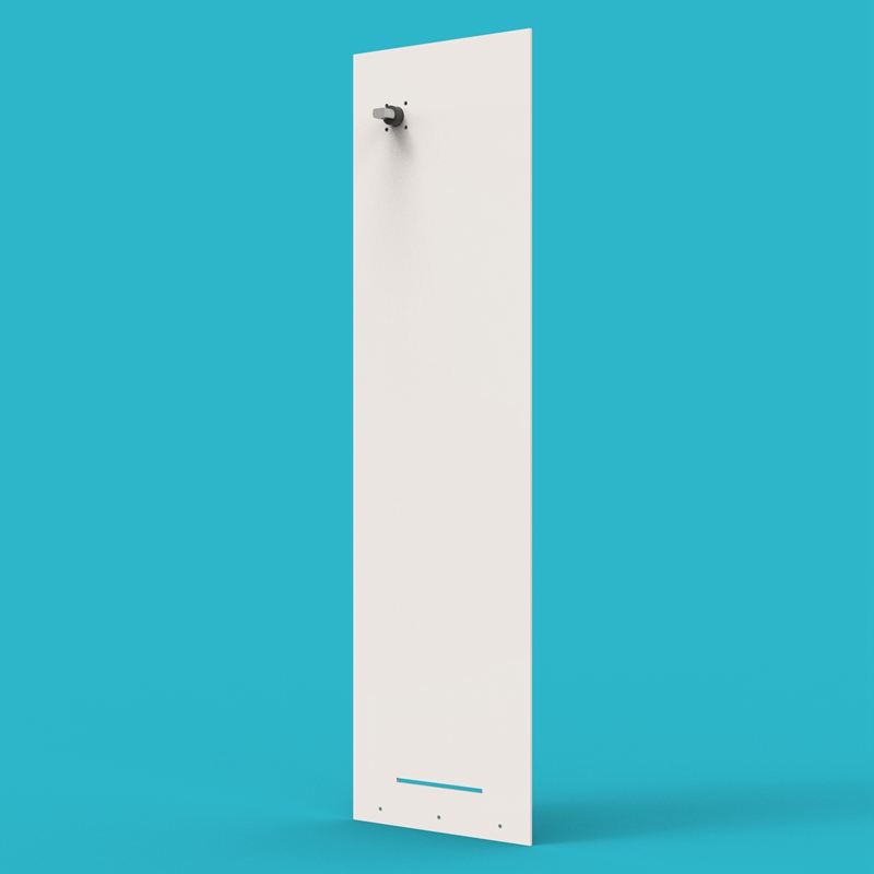
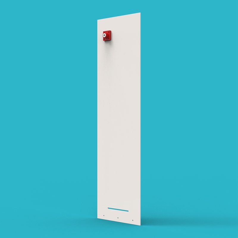
| 05 | Enclosure Side Panel | 2 pcs | 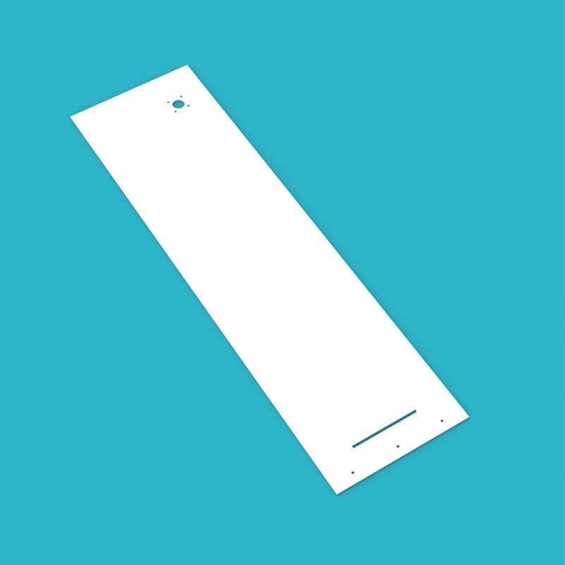 |
| 06 | Enclosure Top Cover | 1 pc |  |
| 07 | Moving Cell Compression Side Plate | 2 pcs | 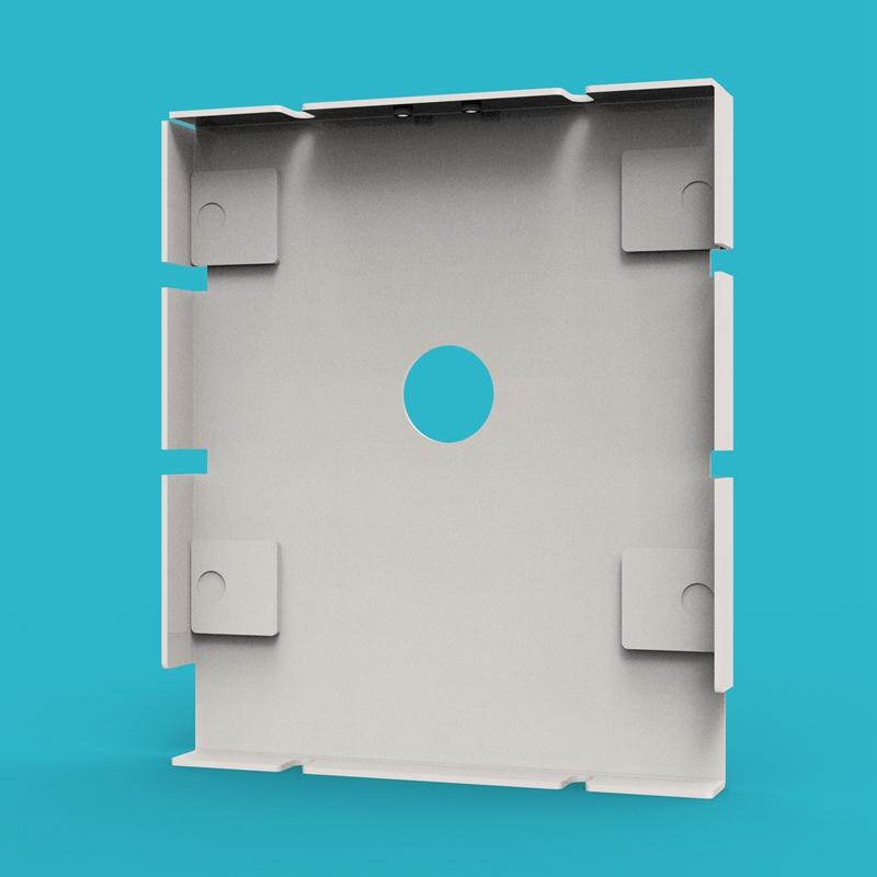 |
| 08 | H-Aluminum Alloy Slot Strip | 4 pcs |  |
| 09 | JK BMS 200A | 1 pc | 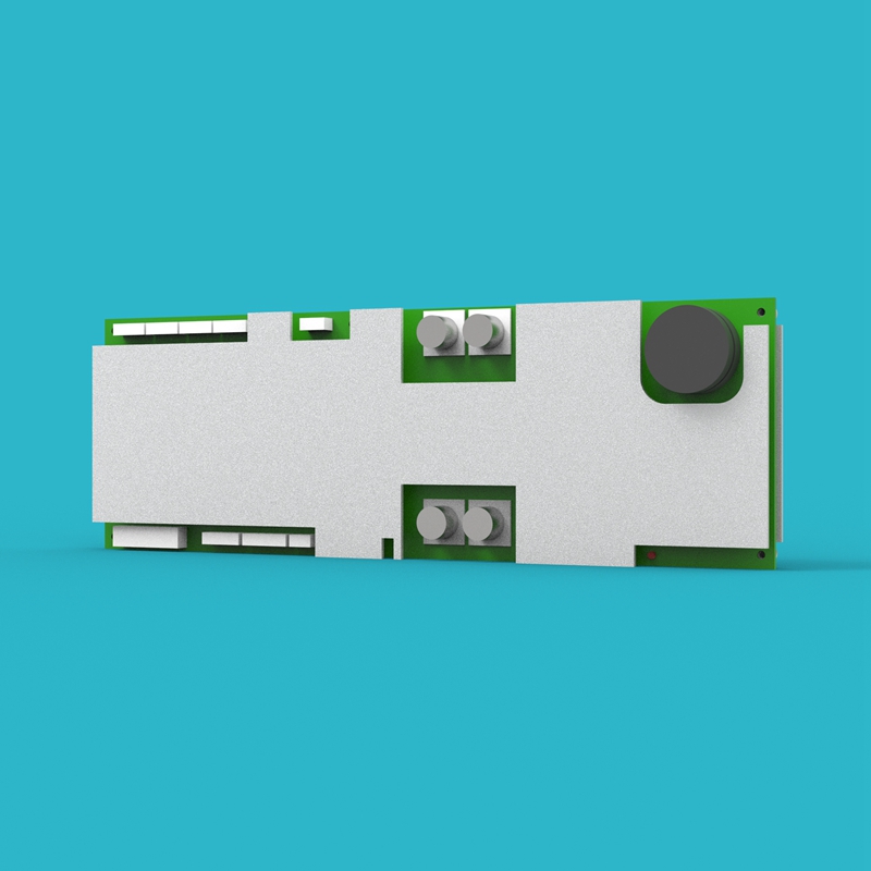 |
| 10 | JK BMS Communication Board | 1 pc | 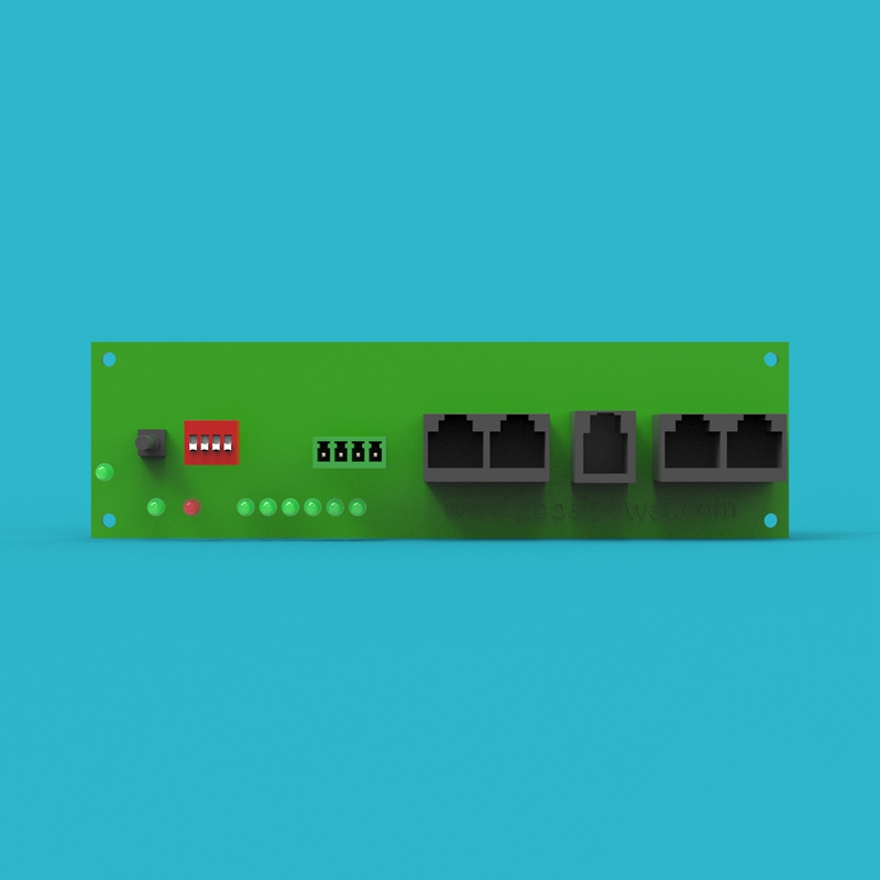 |
| 11 | Voltage Detection PCB Board A | 1 pc |  |
| 12 | Voltage Detection PCB Board B | 1 pc | 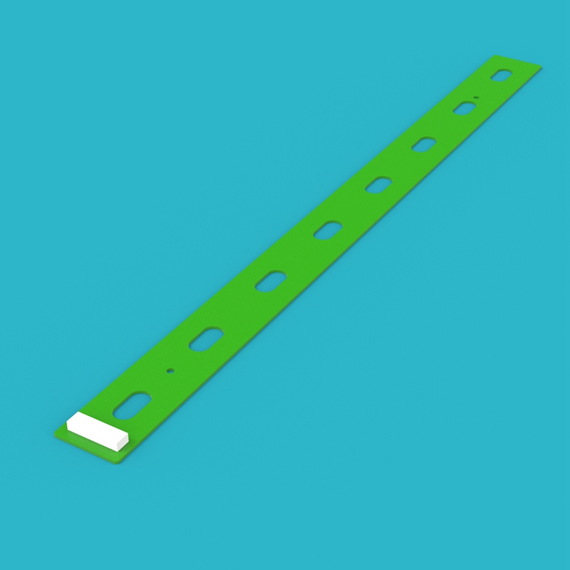 |
| 13 | Cell Epoxy Board | 18 pcs |  |
| 14 | Cell Bottom Insulation Film | 4 pcs | 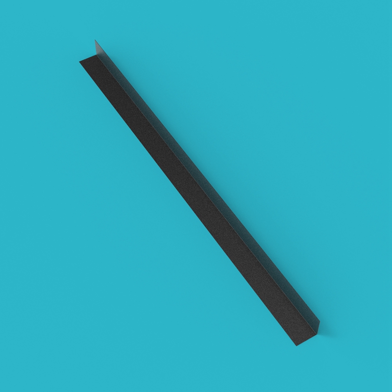 |
| 15 | BMS Mounting Plate | 1 pc | 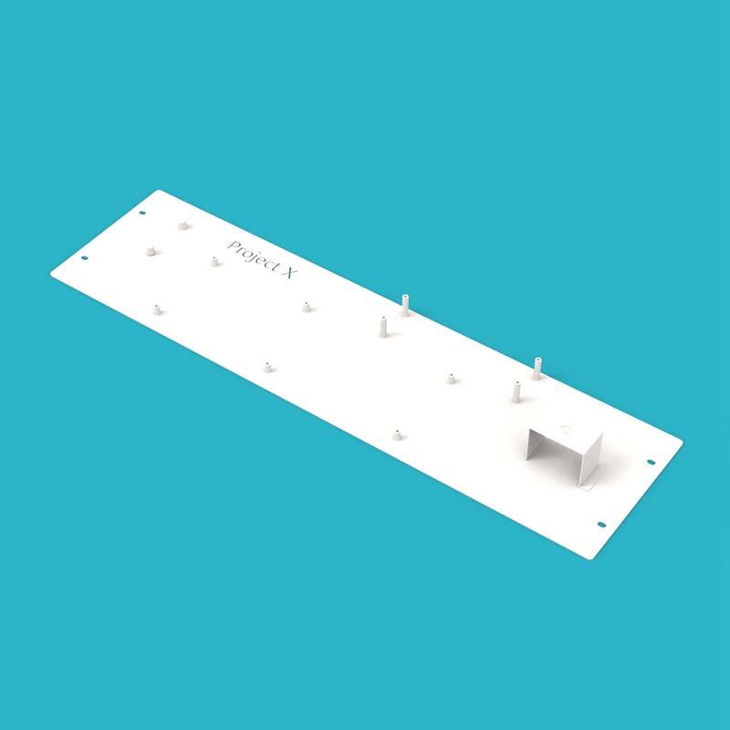 |
| 16 | BMS-Circuit Breaker Busbars | 1 pc |  |
| 17 | Cell 8-9 Busbars | 1 pc |  |
| 18 | Cell Series Busbars | 14 pcs |  |
| 19 | Circuit Breaker-Battery Negative Output Terminal Busbars | 1 pc |  |
| 20 | BMS-Cell Total Negative Busbars | 1 pc |  |
| 21 | Fuse-Cell Total Positive Busbars | 1 pc |  |
| 22 | Fuse-Battery Positive Output Terminal Busbars | 1 pc | 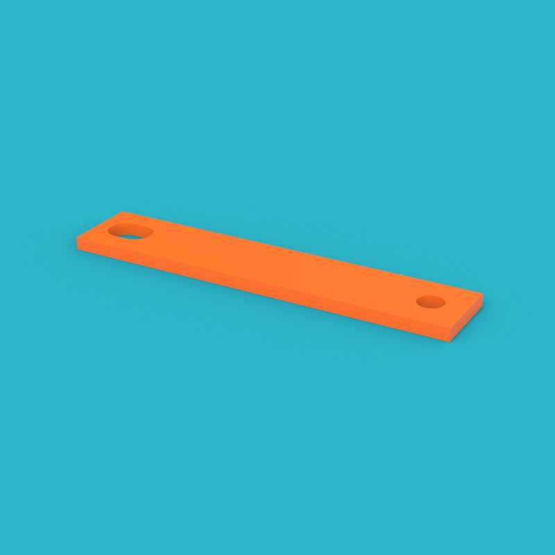 |
| 23 | Circuit Breaker Extension Lug | 4 pcs |  |
| 24 | Cell Metal Pressing Strip | 2 pcs |  |
| 25 | Insulator | 2 pcs |  |
| 26 | USB-RS485(RS232) Communication Cable | 1 pc | 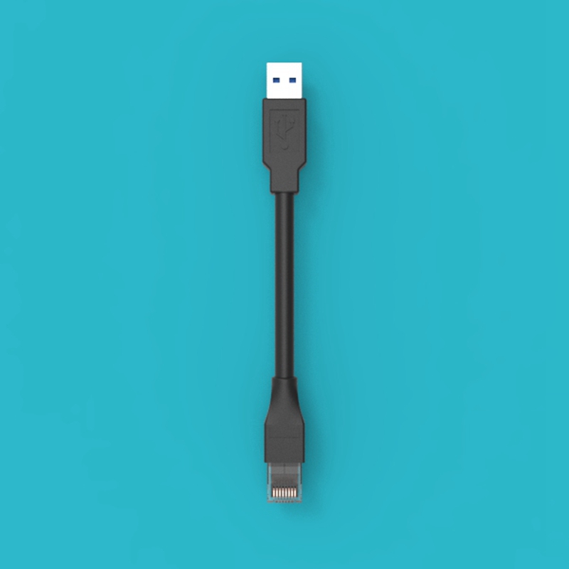 |
| 27 | Battery Negative Output Terminal | 1 pc | 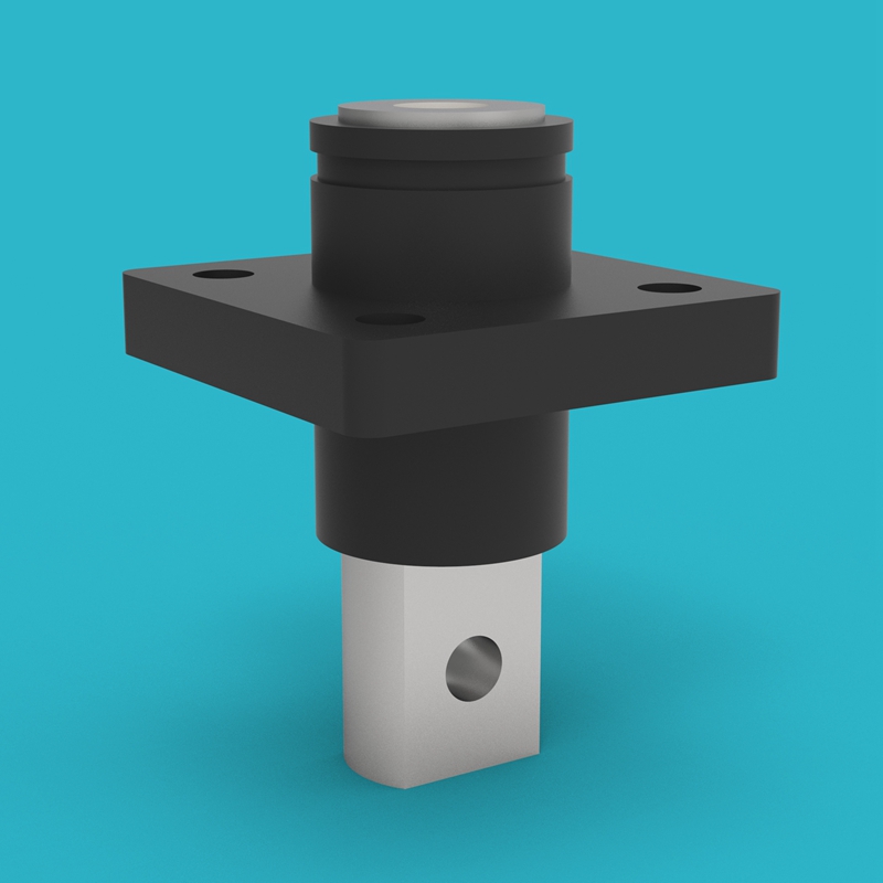 |
| 28 | Battery Positive Output Terminal | 1 pc | 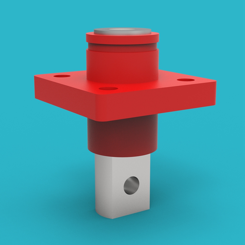 |
| 29 | Metal Push Button Switch | 1 pc | 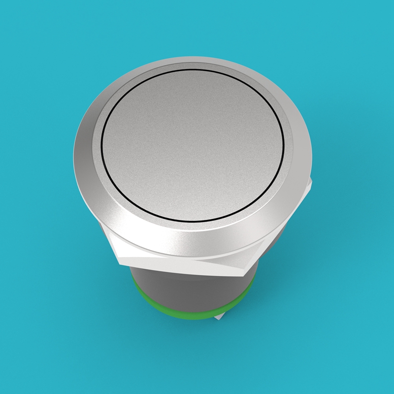 |
| 30 | JK BMS 4.5-inch Screen | 1 pc |  |
| 31 | Caster | 4 pcs (40kg load capacity each) | 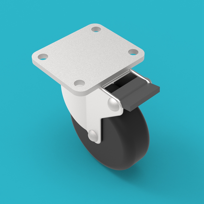 |
| 32 | Circuit Breaker | 1 pc, 2P100A (total 200A) | 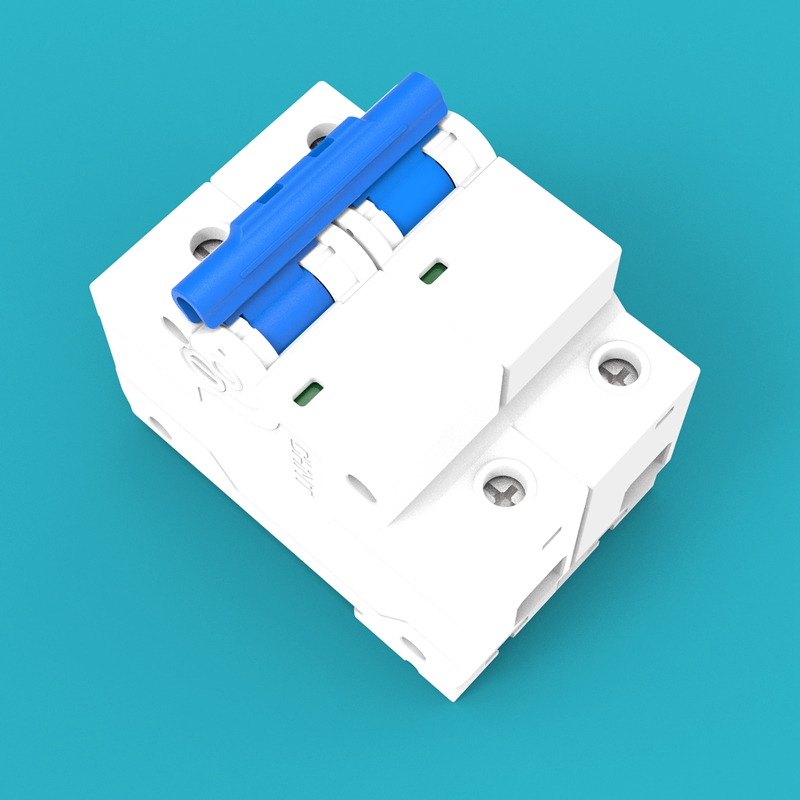 |
| 33 | Fuse | 1 pc, 250A Class-T | 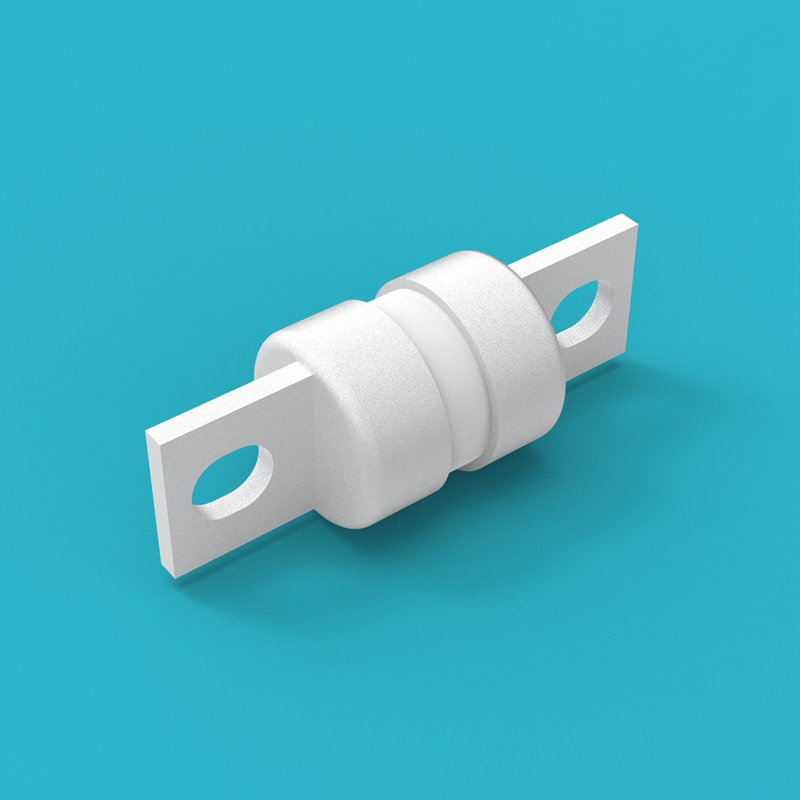 |
Tools and Materials Preparation
The following tools and materials are not included with this kit. Please prepare them yourself before assembly:
| No. | Tool/Material | Specification/Requirement | Purpose |
|---|---|---|---|
| 1 | Screwdriver/Electric Screwdriver | Matching kit screw specifications | Tighten all component fixing screws |
| 2 | Torque Wrench | Range covering 5N.m ~ 20N.m | Tighten screws according to torque requirements |
| 3 | Multimeter | DC voltage measurement range 0V ~ 100V | Detect cell voltage and total voltage |
| 4 | Insulated Gloves | Withstand voltage above 1000V | Electric shock protection during assembly |
| 5 | Safety Glasses | Anti-splash type | Prevent metal debris or sparks from injuring eyes |
| 6 | Workbench | Stable, flat, insulated surface | Place and assemble all components |
Please ensure all tool insulated handles are intact. Metal-exposed tools may cause short circuits when touching cells.
Screw Torque Requirements
To ensure all connection points are reliably tightened without over-tightening and causing damage, please operate according to the following torque requirements:
| Screw Specification | Torque Requirement |
|---|---|
| M5 | 5N.m |
| M6 | 8N.m |
| M8 | 15N.m |
| M10 | 15-20N.m |
Use a torque wrench to tighten screws according to the above requirements. Insufficient torque may cause loose connections and overheating; excessive torque may damage threads or components.
Module Assembly
Before starting the main assembly, the following modules need to be pre-assembled.
1. Base Assembly
Place the Base (01) on the workbench, and install the Casters (31) on the four corners of the base bottom, ensuring the caster directions are consistent and they can rotate normally.
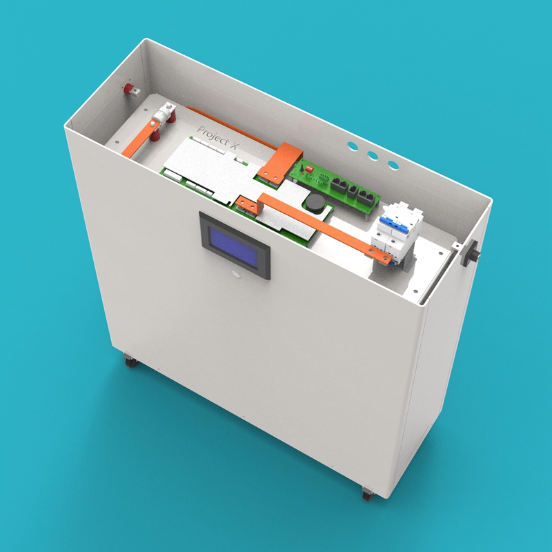
2. Enclosure Front Panel Assembly
Place the Enclosure Front Panel (04) face up, and install the JK BMS 4.5-inch Screen (30) and Metal Push Button Switch (29) into the corresponding openings on the enclosure front panel, securing them with screws.
3. Negative Enclosure Side Panel Assembly
Lay one Enclosure Side Panel (05) flat, and install the Battery Negative Output Terminal (27) onto the corresponding position on the side panel, securing it with screws. Confirm the terminal orientation is correct.
4. Positive Enclosure Side Panel Assembly
Lay the other Enclosure Side Panel (05) flat, and install the Battery Positive Output Terminal (28) onto the corresponding position on the side panel, securing it with screws.
The negative enclosure side panel assembly and the positive enclosure side panel assembly are mirror images. Be sure to confirm the terminal orientation is correct during installation to avoid orientation errors during subsequent main assembly.
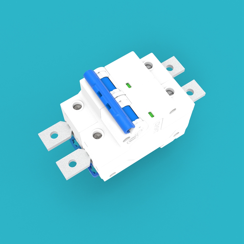
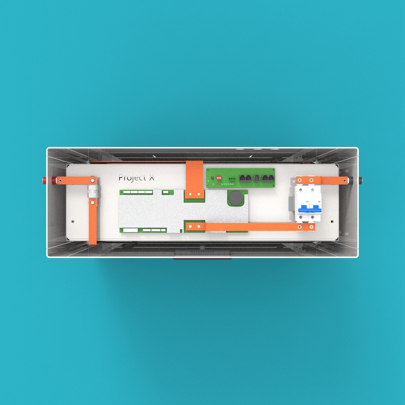
5. Circuit Breaker Assembly
Insert the Circuit Breaker Extension Lugs (23) into the four terminal ports of the Circuit Breaker (32) respectively, and secure them with screws. Ensure each lug has good contact with the terminal port.
6. BMS Assembly
Use the BMS Mounting Plate (15) as the base, and install the following components in sequence:
- Install the JK BMS 200A (09) onto the BMS mounting plate
- Install the JK BMS Communication Board (10) next to the BMS
- Install the Insulators (25) onto the corresponding positions of the mounting plate (for fixing the fuse)
- Install the Fuse (33) onto the insulators
- Install the assembled Circuit Breaker Assembly onto the BMS mounting plate
- Use the BMS-Circuit Breaker Busbars (16) to connect the BMS and circuit breaker
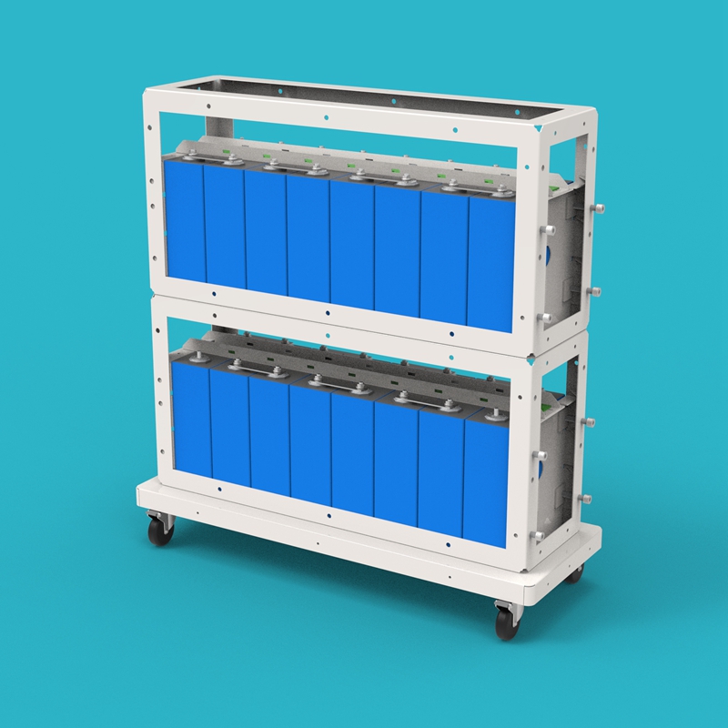
7. Lower Cell Module Assembly (Cells 9-16)
Lay the Metal Frame (02) flat on the workbench, and assemble the lower cell module according to the following steps:
a. Observe the metal frame; one side has a fixed side plate. When facing the metal frame, keep the fixed side plate on the left.
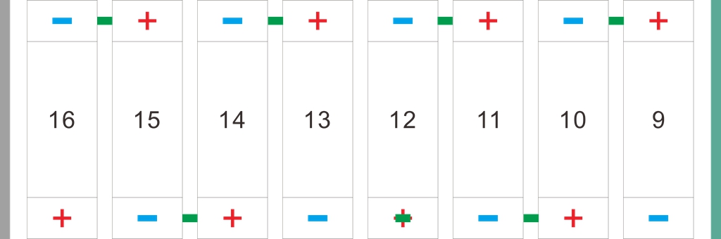
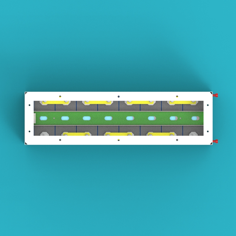
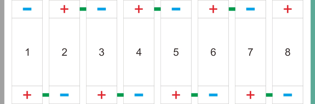
b. Lay the Cell Bottom Insulation Film (14) on the bottom of the metal frame. Place the cells according to the diagram, and use the Cell Series Busbars (18) to connect the cells in series sequentially.
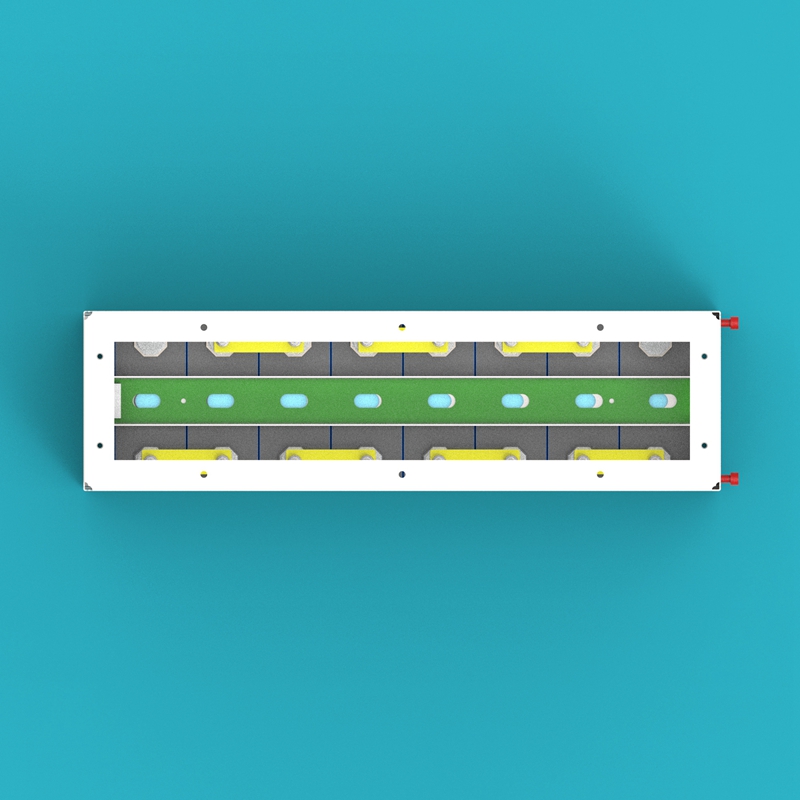
The left side in the image is the fixed side plate, and the right side is the moving cell compression side plate.
c. Install the Moving Cell Compression Side Plate (07) on the other side of the metal frame, and adjust the compression force on the cells by adjusting the 4 screws on the side plate, ensuring the cells are tightly arranged but not excessively squeezed.
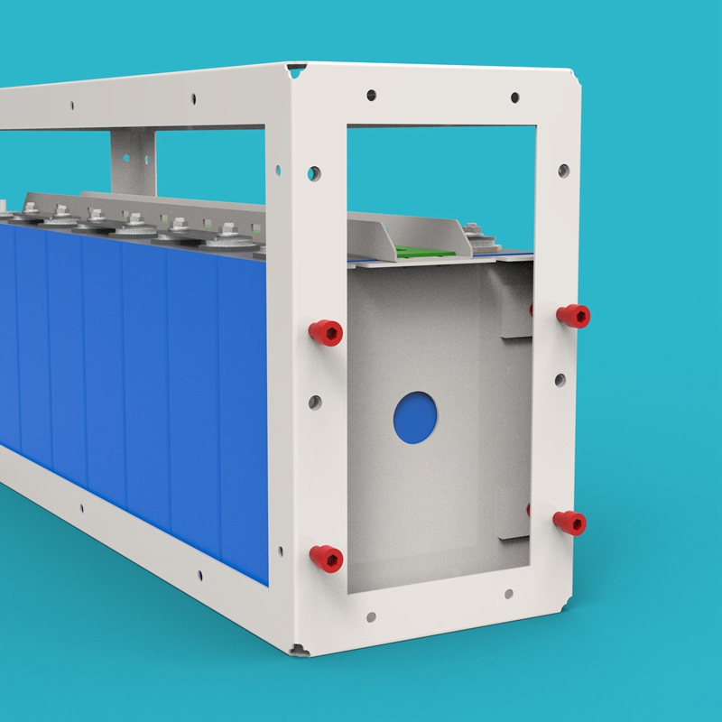
d. Place the Cell Metal Pressing Strip (24) on top of the cells, and secure them with screws onto the fixed side plate and the moving cell compression side plate.
One end of the cell metal pressing strip has a long slotted hole; this end should face the moving cell compression side plate to accommodate the side plate position adjustment.
e. Place the Voltage Detection PCB Board B (12) on the cell metal pressing strip, with the end of the PCB board with terminals facing left. Then connect the detection wires on Voltage Detection PCB Board B to the corresponding cell busbars sequentially.
8. Upper Cell Module Assembly (Cells 1-8)
The assembly method for the upper cell module assembly is the same as the lower cell module assembly. The differences are:
- The position layout of the cell busbars is different (please refer to the diagram)
- Use Voltage Detection PCB Board A (11) instead of Voltage Detection PCB Board B
Main Assembly
After completing all module pre-assembly, proceed with the main assembly according to the following steps.
1. Place Base Assembly
Place the assembled base assembly on the ground, and check whether all four Casters (31) are securely fixed and can rotate and lock normally.
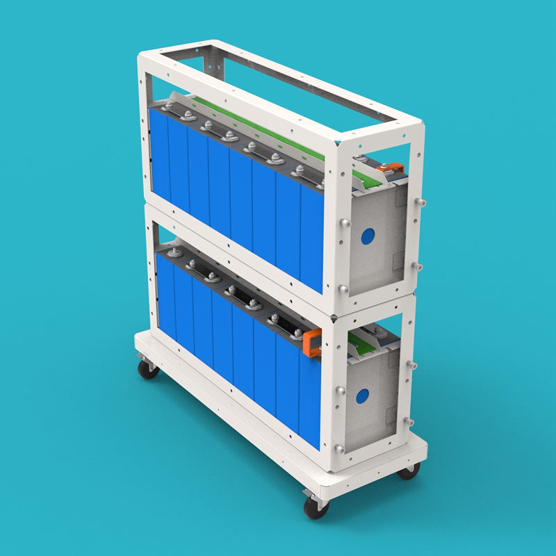
2. Install Lower Cell Module
Carefully place the lower cell module assembly onto the base, and use screws to securely fix the cell module to the base.
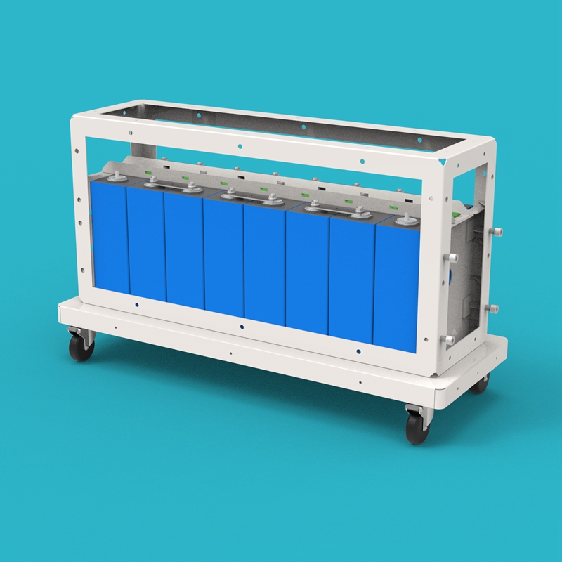
3. Install Upper Cell Module
Place the upper cell module assembly on top of the lower cell module assembly, ensuring the moving cell compression side plates of the upper and lower modules are on the same side. Use screws to fix the upper and lower cell modules together.
4. Connect Cell 8 and Cell 9
Use the Cell 8-9 Busbars (17) to connect Cell 8 at the top of the lower module with Cell 9 at the bottom of the upper module, completing the series connection of the 16 cells.
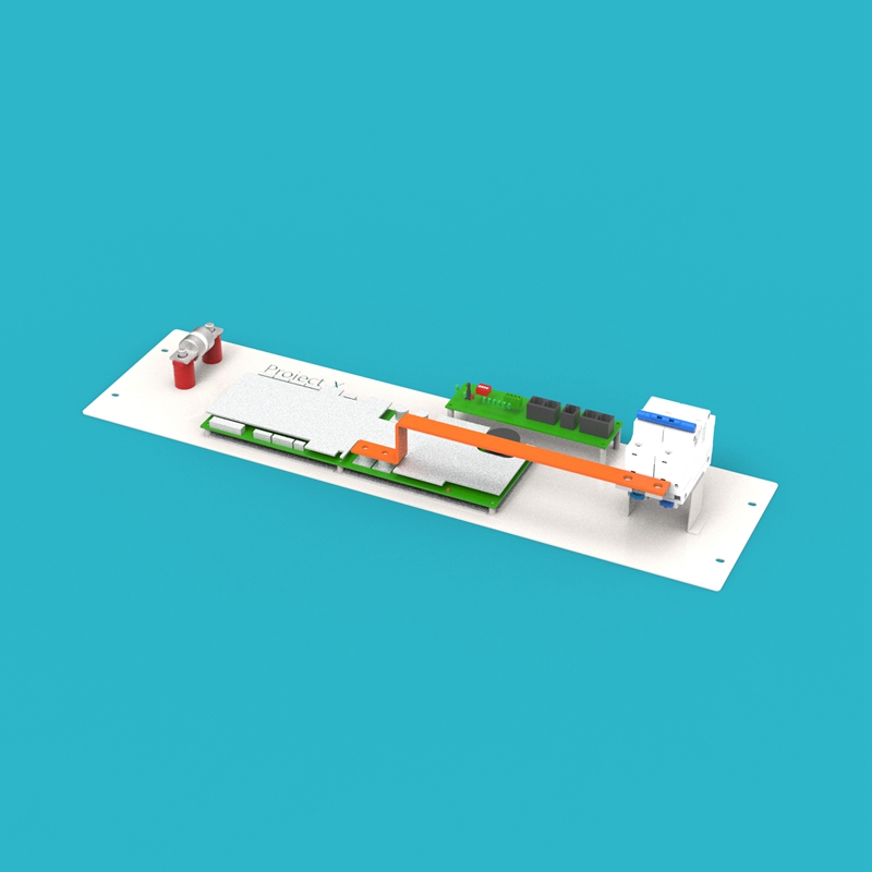
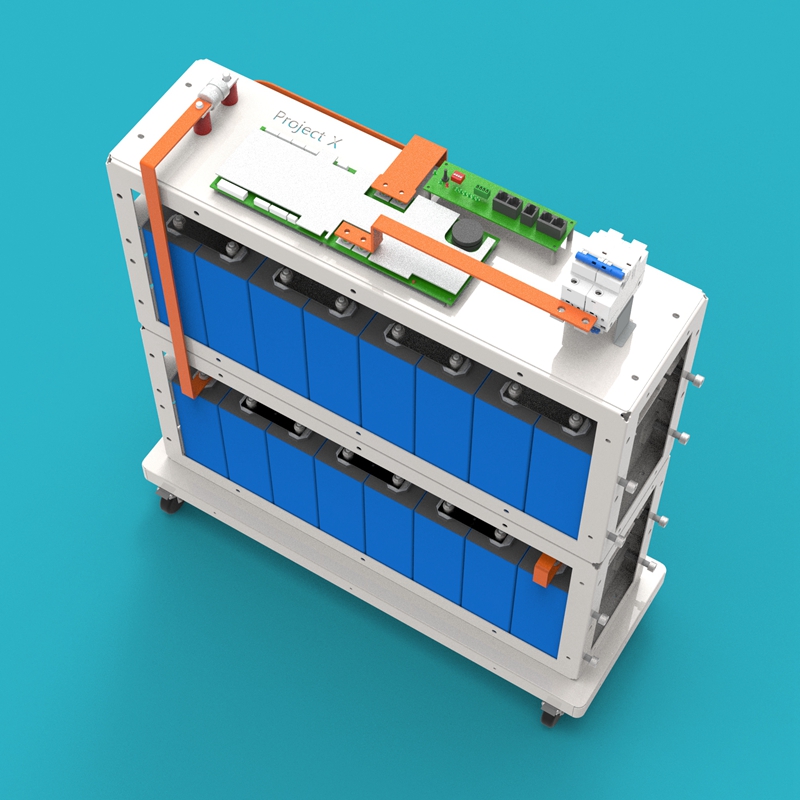
5. Install BMS Assembly
Fix the BMS assembly on top of the upper cell module assembly, with the fuse side facing left. Use screws to securely fix the BMS mounting plate to the cell module frame.
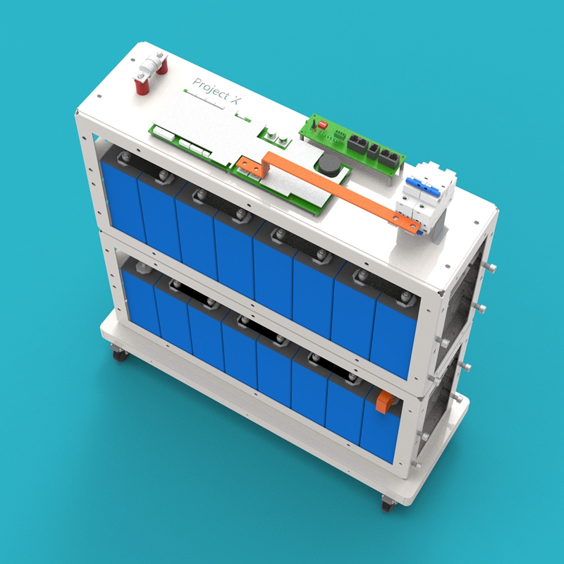
6. Connect Main Circuit and Detection Wires
- Use the Fuse-Cell Total Positive Busbars (21) to connect the positive pole of Cell 16 with the Fuse (33)
- Use the BMS-Cell Total Negative Busbars (20) to connect the negative pole of Cell 1 with the JK BMS 200A (09)
- Use communication cables to connect the voltage detection PCB boards with the BMS
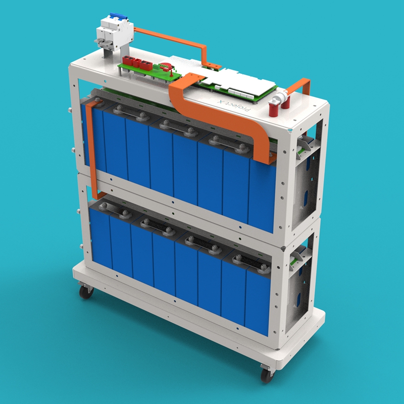
7. Install Enclosure Assembly
Install each enclosure assembly onto the base, positive side panel on the left, negative side panel on the right. Connect the cables of the JK BMS 4.5-inch Screen (30) and Metal Push Button Switch (29) to the BMS.
8. Connect Output Terminals
- Use the Circuit Breaker-Battery Negative Output Terminal Busbars (19) to connect the circuit breaker with the Battery Negative Output Terminal (27)
- Use the Fuse-Battery Positive Output Terminal Busbars (22) to connect the fuse with the Battery Positive Output Terminal (28)
9. Secure Enclosure Side Panels
Insert the H-Aluminum Alloy Slot Strips (08) into the gaps between the enclosure side panels and the enclosure front/back panels, and secure all enclosure side panels one by one.
10. Install Enclosure Top Cover
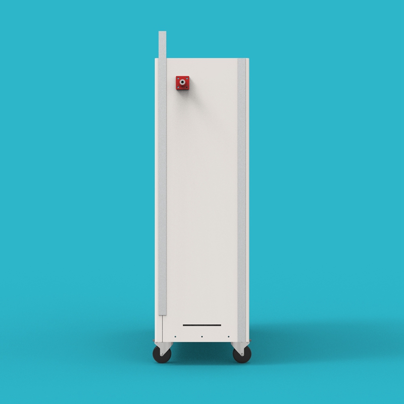
Place the Enclosure Top Cover (06) on top of the battery, ensuring the top cover is aligned with all sides of the enclosure and sits steadily.
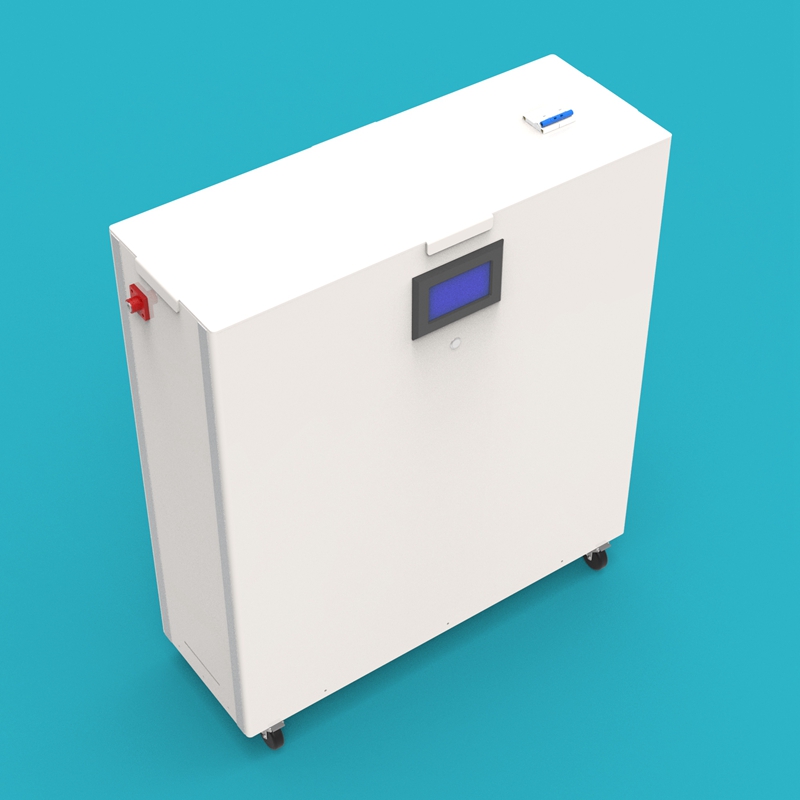
11. Assembly Complete
Check whether all screws are tightened, all busbars are installed in place, and all cables are connected correctly. After confirmation, the GP-Project-X battery kit assembly is complete.
Contact Information
If you encounter any unresolved issues or have any questions, please contact Gobel Power technical support:
- Official Website: www.gobelpower.com
- Technical Support Email: [email protected]