GP-PWB1-PC200B WIFI Module Installation and Configuration Manual
Safety Instructions
Before inserting or removing the WIFI module, please ensure that the battery is powered off to prevent potential arcing or interface damage caused by live plugging.
- Do not use or store the module in damp, high-temperature, or corrosive gas environments.
- The module consists of precision electronic components; please avoid severe vibration, impact, or falling.
- Ensure that the sealing cap installed on the module is tightened to prevent dust and moisture from entering the battery terminals.
Product Introduction
The GP-PWB1-PC200B WIFI module is a remote communication adapter designed specifically for the latest GP-PC200B BMS batteries equipped with a WIFI port.
Used in conjunction with the Gobel VRM online platform and the Gobel VRM App (supporting Android and iOS), this module enables centralized monitoring and management of a single battery or up to 63 parallel battery packs.
Main Features
- Real-time Monitoring: Records and displays the current, voltage, temperature of each battery, and the individual cell voltages.
- Parameter Setting: Allows users to set the maximum voltage, maximum charging current, and maximum discharging current requested from the inverter.
- High-frequency Update: Data update frequency can be as fast as every 10 seconds.
- Historical Tracking: Cloud historical records can be stored for up to 6 months.
- Parallel System Support: Only one module is required to monitor the entire parallel battery system.
Parts List
| No. | Name | Specification/Quantity | Image |
|---|---|---|---|
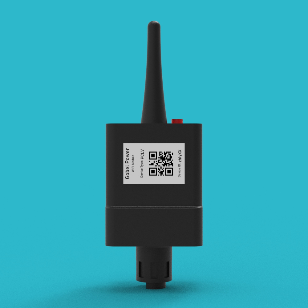
| 01 | WIFI Communication Module | 1 pc | 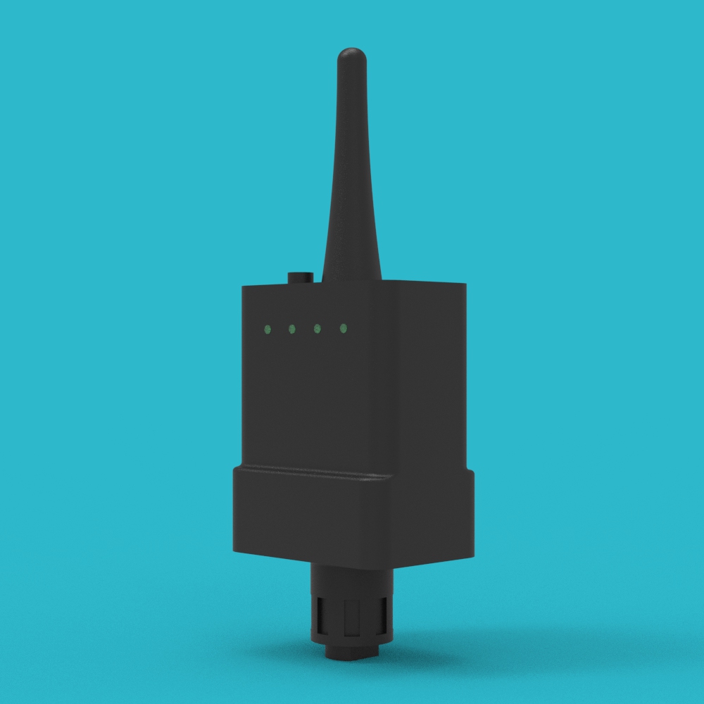 |
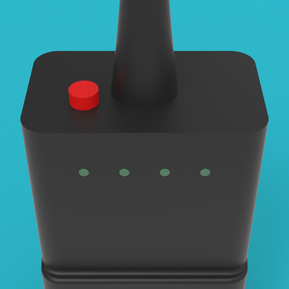
This module contains an integrated 2.4GHz WIFI antenna and LED status indicators to show network pairing and operating status.
Installation Steps
1. Confirm Port
Confirm that the battery panel has a dedicated WIFI port (WIFI Connector).
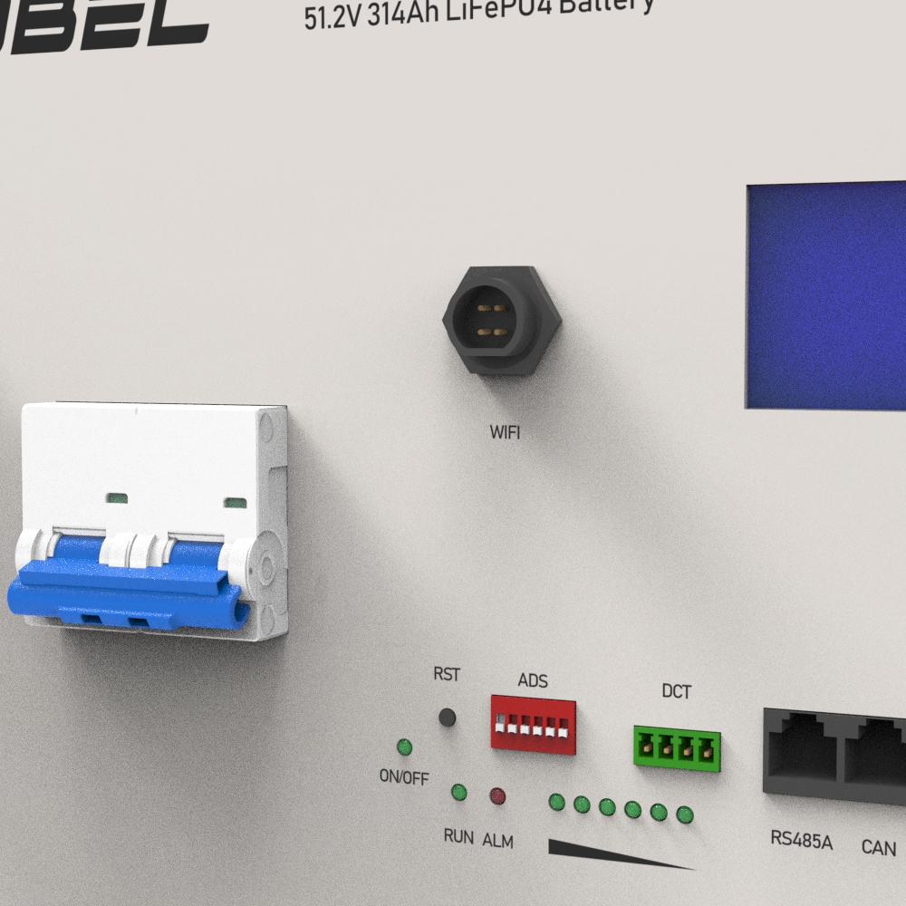
2. Insert Module
Insert the WIFI Communication Module (01) fully into the WIFI port on the battery panel according to the specific orientation of the interface keyway.
3. Secure Sealing Cap
Tighten the built-in sealing cap of the WIFI Communication Module (01) clockwise to ensure a firm physical connection and meet protection requirements.
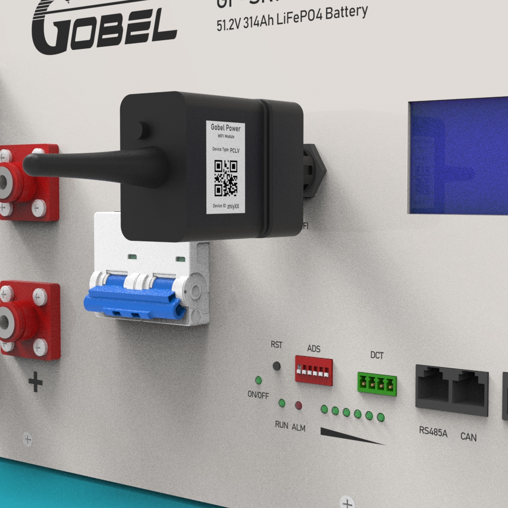
4. Confirm Installation
Power on the battery and observe whether the indicator light on the WIFI Communication Module (01) lights up. If the light is on, the physical connection of the module installation is complete.
Configuration and Pairing Process
- The WIFI module only supports 2.4GHz WIFI networks (5GHz is not supported).
- Please download the Gobel VRM App from Google Play or the App Store before starting the operation.
- The phone must have Bluetooth enabled during the network pairing process.
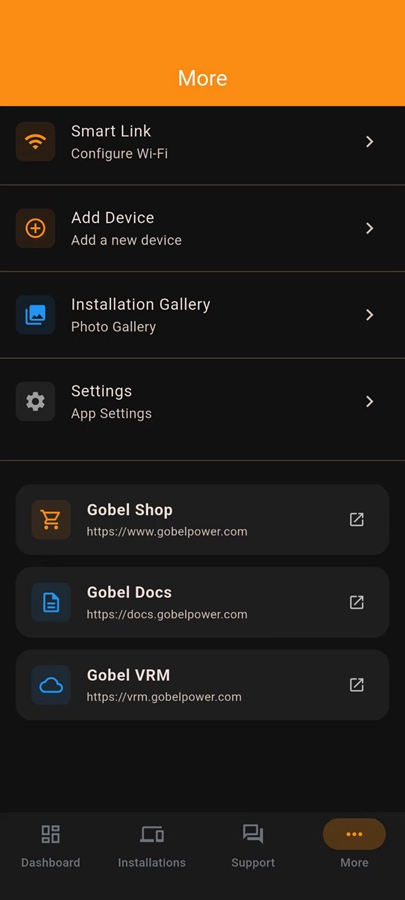
1. Software Preparation
Open the Gobel VRM App on your phone. Tap the More tab at the bottom of the App, and then tap Smart Link.
2. Mode Activation
Short press the circular configuration button on the top of the module (hold for about 1-2s). The module indicator should start flashing rapidly at this time, indicating that the module has entered provisioning mode.
3. WIFI Login
On the Smart Link page, enter the 2.4GHz WIFI hotspot name and password you wish to connect to. You can tap the WIFI icon to scan and select available 2.4GHz WIFI hotspots.
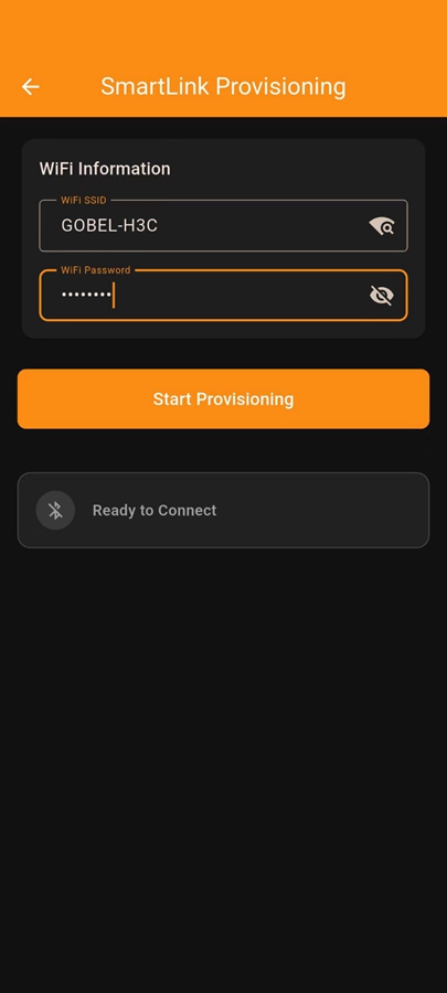
4. Automatic Pairing
Tap the Start Provisioning button. The system will automatically perform WIFI pairing settings for the WIFI Communication Module (01).
5. Status Confirmation
After successful pairing, the indicator on the module will change from rapid flashing to a steady light or normal communication state (the light stops flashing rapidly).
6. Add Device
Return to the More page of the App and tap Add Device. Before proceeding to the next step, find the Device ID and Device Type on the side label of the WIFI Communication Module (01).
7. Data Entry
Enter the following information on the Add Device page:
- Device ID: It is recommended to tap the QR code icon to scan for input.
- Installation Name: You can customize the name for this system.
- Device Type: Please select the device type that matches the module label.
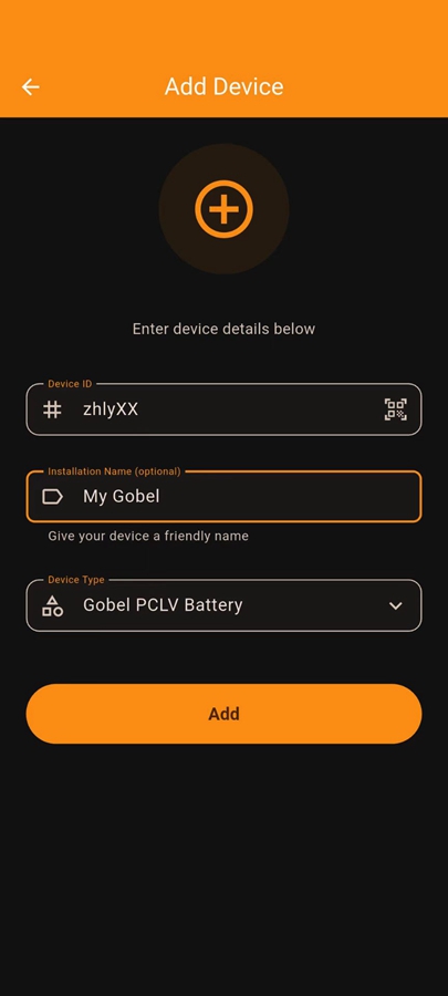
8. Complete Configuration
Tap the Add button to complete the addition. Now you can view the battery monitoring information in real-time on the Installations page.
FAQ
1. How to use when multiple batteries are in parallel?
When multiple batteries are connected in parallel, only one WIFI module is needed. Insert it into the WIFI port of the battery set as the Master in the parallel system to monitor the entire cluster.
2. Use on older GP-PC200 BMS
The older GP-PC200 BMS does not have a dedicated WIFI port and cannot have this module installed directly. However, through parallel technology, you can use one battery with the latest GP-PC200B BMS as the master battery and install the module, thereby reading data from all older GP-PC200 BMS batteries connected in parallel under the system.
3. How to mix old and new BMS to achieve more than 16 units in parallel?
The older GP-PC200 BMS has a 4-bit DIP switch (addresses 1-16), while the new GP-PC200B BMS has a 6-bit DIP switch (addresses 1-63).
- Mixing Principle: One GP-PC200B BMS battery must be set as Master Battery No. 1.
- Address Allocation: Set the older BMS batteries as units 2-16. Starting from unit 17, the new GP-PC200B BMS batteries must be used again.
- Configuration Requirement: Unique ID addresses must be manually assigned via DIP switches for all batteries participating in parallel (regardless of whether they are new or old models).