GP-PC200B BMS connection and setup guide for Deye hybrid inverters

This manual describes how to physically connect and set parameters for a battery pack equipped with GP-PC200B BMS to a Deye hybrid inverter, enabling normal communication between the battery and the inverter via the CAN protocol.
Applicable products: Gobel Power GP-PC200B BMS paired with Deye hybrid inverter series.
Required Materials
The following materials and equipment are required for this connection setup.
| No. | Name | Description |
|---|---|---|
| 1 | Battery pack with GP-PC200B BMS | The battery pack must have the GP-PC200B BMS properly installed and operating normally |
| 2 | Deye hybrid inverter | A Deye hybrid inverter supporting CAN communication protocol |
| 3 | Ethernet cable (straight-through) | A straight-through Ethernet cable with symmetrical RJ45 connector pinouts on both ends, used to connect the BMS to the inverter |
Please ensure the Ethernet cable used is a straight-through cable with symmetrical ends (not a crossover cable), and that the RJ45 connectors on both ends are intact and secure. Choose the cable length based on the actual installation position; it is recommended not to exceed 10 meters to ensure communication stability.
Connection & Setup
The following steps will guide you through BMS protocol configuration, physical connection, and inverter parameter settings.
BMS Communication Protocol Setup
First, set the CAN communication protocol of the GP-PC200B BMS to Deye-compatible mode.
- Log in to the GP-PC200B BMS management interface
- Enter the communication protocol settings page
- Set the CAN communication protocol to Deye or Pylon mode
Deye inverters are compatible with both Deye and Pylon CAN communication protocols. If one protocol fails to communicate properly, try switching to the other.
For detailed BMS protocol setup steps, please refer to the official documentation:
GP-PC200B Communication Protocol Setup Guide
Physical Connection
Use an Ethernet cable to physically connect the BMS to the inverter.
- Confirm that both the battery pack and inverter are powered off
- Take the Ethernet cable (straight-through) and insert one end into the master battery's CAN port
- Insert the other end of the Ethernet cable into the Deye inverter's BMS port
The battery should be properly addressed via DIP switches. For details, see the GP-PC200B Communication Protocol Setup Guide.
Before connecting, make sure both devices are powered off. Hot-plugging communication cables may cause damage to the communication interfaces.
Inverter Parameter Settings
After completing the physical connection, power on the inverter and configure the following settings on the inverter's touch screen.
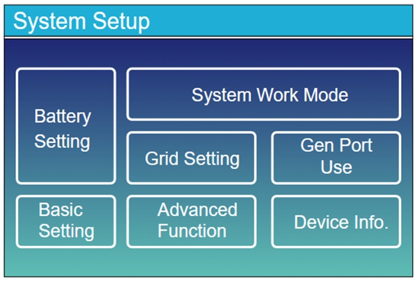
Step 1: Enter the Battery Settings Page
On the inverter's home screen, tap to enter the System Setup page, then tap the Battery Setting option.
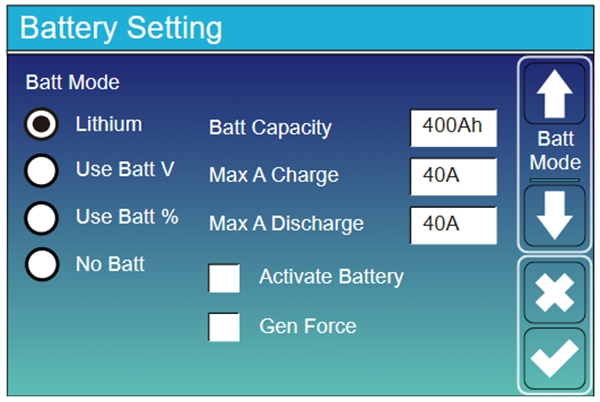
Step 2: Configure Battery Parameters
On the Battery Setting page, configure the following parameters in order:
- Batt Mode: Select Lithium
- Batt Capacity: Enter the total battery pack capacity. Formula: rated capacity on the battery label × number of batteries
- Max A Charge: Enter the maximum charging current of the battery pack. This value should be less than or equal to the maximum continuous charging current on the battery label × number of batteries
- Max A Discharge: Enter the maximum discharging current of the battery pack. This value should be less than or equal to the maximum continuous discharging current on the battery label × number of batteries
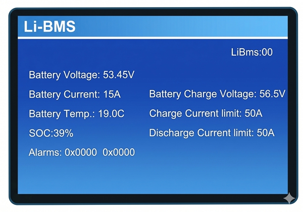
Step 3: Verify BMS Communication Data
After completing the parameter settings, navigate to the Li-BMS page on the inverter screen to view the real-time data read by the inverter from the battery BMS. Check the following items one by one:
| Check Item | Correct Value |
|---|---|
| Battery Voltage | Should equal the average battery voltage |
| Battery SOC | Should equal the average battery SOC |
| Charge Current Limit | Should equal the maximum charging current value calculated in the previous step |
| Discharge Current Limit | Should equal the maximum discharging current value calculated in the previous step |
Step 4: Confirm Communication is Normal
If all the above data is verified correctly, it indicates that CAN communication between the battery and the inverter has been successfully established, and the connection setup is complete.
For more inverter setting options, please refer to the official Deye inverter manual: www.deyeinverter.com
Appendix
Reference Links
| Resource | Link |
|---|---|
| GP-PC200B BMS Communication Protocol Setup | https://docs.gobelpower.com/docs/bms/GP-PC200B/communication/ |
| Deye Inverter Official Manual | https://www.deyeinverter.com/ |
FAQ
Q: No data displayed on the inverter Li-BMS page?
A: Please check the following:
- Confirm that the master battery's DIP switch addressing is correct
- Confirm that the BMS CAN communication protocol is correctly set to Deye or Pylon mode
- Check that both ends of the Ethernet cable are firmly inserted into the CAN port and BMS port
- Confirm that the Ethernet cable is a straight-through cable and rule out cable defects
- Try powering off both the inverter and BMS, then restarting
Q: The battery data displayed on the inverter does not match actual values?
A: Confirm that the BMS CAN communication protocol is correctly set to Deye or Pylon mode.