GP-SRA-PC314 Assembly Manual
Brand: Gobel Power
Product Model: GP-SRA-PC314
Manual Type: Assembly Manual
Applicable Product: LiFePO4 High Voltage Battery DIY Kit
Safety Precautions
- The system voltage can reach up to 1000V. During installation, commissioning, and use, safety precautions must be taken according to relevant safety regulations to avoid accidents.
- It is strictly forbidden to connect the slave BMU while the high-voltage box is powered on to avoid potential damage to the BMS.
- Tools used by installation and commissioning personnel must have insulation protection.
- Insulated rubber gloves must be worn during installation, commissioning, and maintenance. Wear goggles and insulated rubber boots as appropriate to avoid accidents as much as possible.
- When maintenance is required, the main circuit breaker must be disconnected to cut off the connection between the battery pack and the PCS DC bus.
- If wire ends, metal, or other debris generated during installation, commissioning, and maintenance fall into the battery compartment, be sure to use insulated tools to remove them. Do not leave debris inside.
- Ensure the positive and negative poles are connected correctly to avoid short circuits that could damage the battery or BMS.
- In case of a fire around the energy storage cabinet, be sure to use a dry powder fire extinguisher or fire sand to extinguish the fire.
- Using liquid to extinguish the fire may result in electric shock.
- If the system is not used for a long time, be sure to disconnect the main circuit breaker of the battery cabinet.
- The working environment should be kept dry, ventilated, and free of flammable materials.
- Children and unrelated personnel should stay away from the installation area.
- Use qualified tools with insulation protection for operation.
Product Introduction
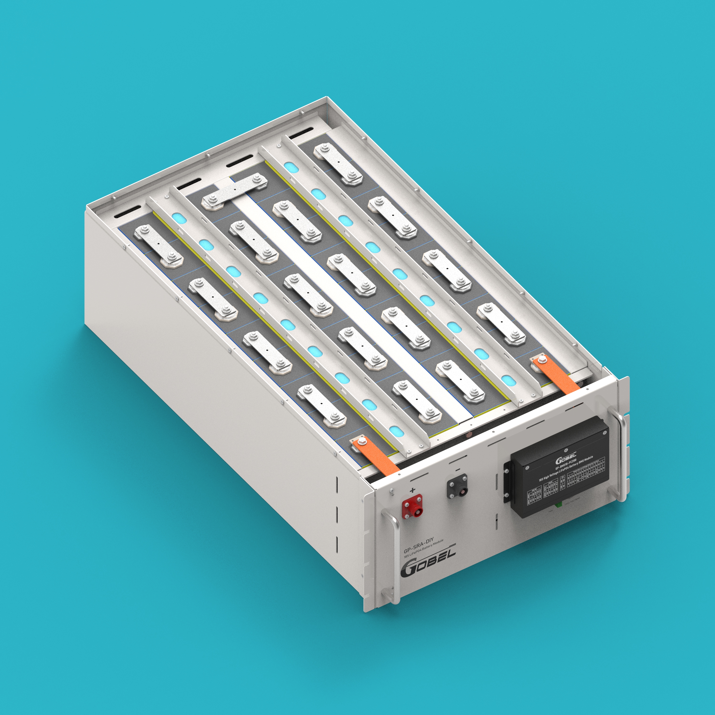
GP-SRA-PC314 is a LiFePO4 high-voltage battery DIY kit launched by Gobel Power, consisting of three main parts: high-voltage box, BMU, and battery pack.
Main Features
- Cell Specification: Uses 314Ah LiFePO4 cells
- Connection Method: 1P18S series (18 cells in series)
- System Configuration: This high-voltage system requires at least 5 battery packs and a maximum of 15 battery packs connected in series.
- BMU Function: Each battery pack is equipped with one BMU, which can detect the voltage of 18 cells and is equipped with 8 NTC temperature sensors.
- High-Voltage Box Performance:
- Supports a maximum current of 200A
- Can connect to inverters, upper computers, and EMS
- Provides overcharge protection, over-discharge protection, over-current protection, over-temperature protection, low-temperature protection, and multi-level alarm mechanisms
- Real-time communication with the master controller to upload battery data
- Battery status and data storage functions
- RS485 and CAN isolated communication functions
- Can be externally connected to 6 relays, suitable for commercial and industrial energy storage, UPS power supply systems, and other applications
Parts List
The quantity marked "N" in the table below represents the quantity required for each battery pack. The high-voltage box and some common parts only require 1 piece.
| No. | Name | Specification/Quantity | Image |
|---|---|---|---|
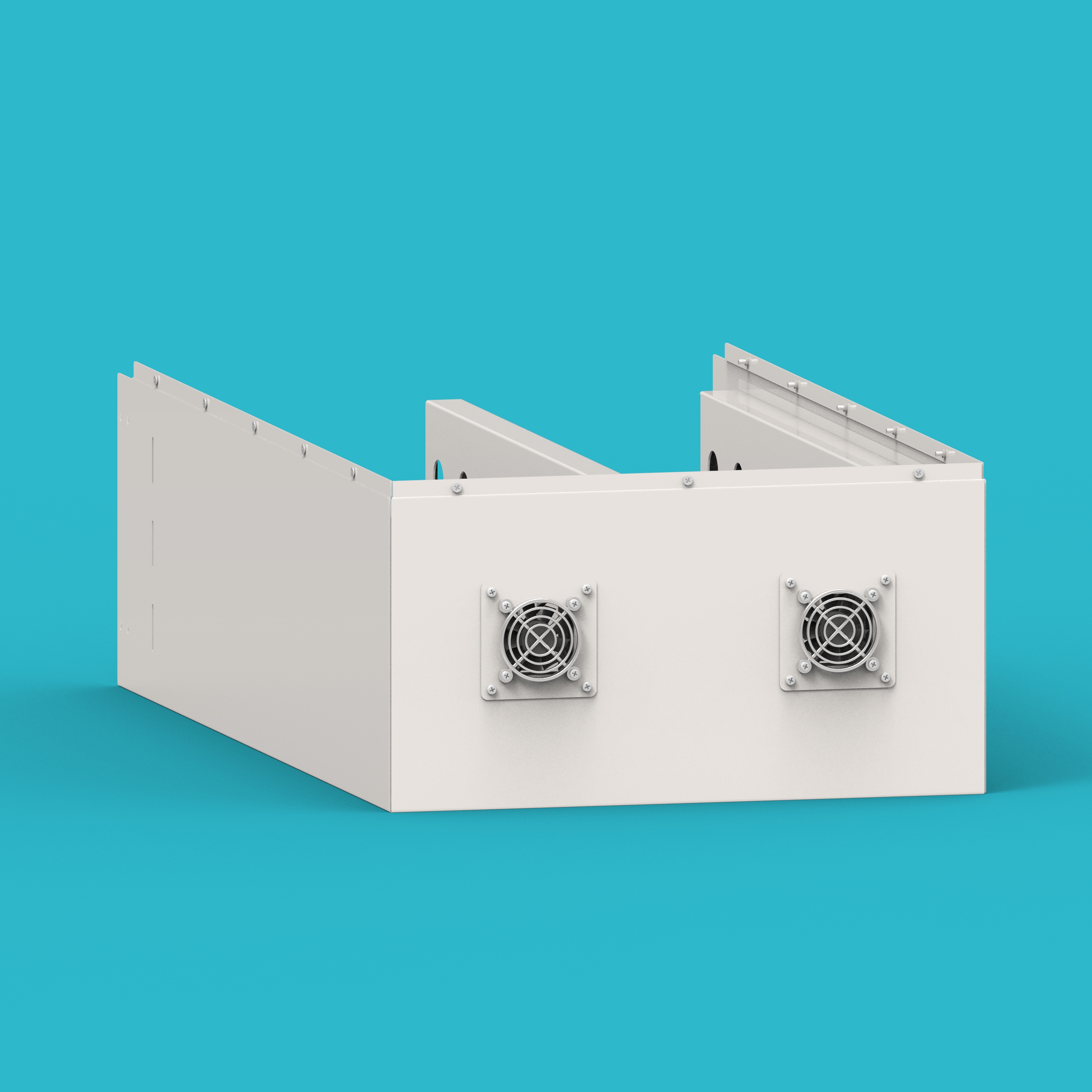
| 01 | Enclosure Case | 1 pc/N | 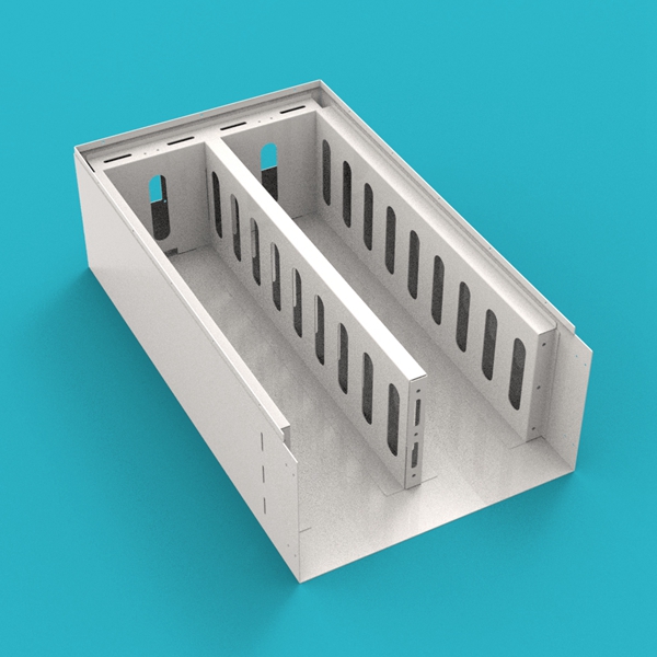 |
| 02 | Cell Compression Plate | 1 pc/N | 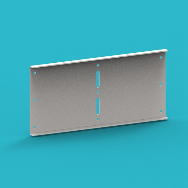 |
| 03 | Cell Clamping Bar | 1 pc/N |  |
| 04 | Bottom Epoxy Board | 2 pcs/N |  |
| 05 | Side Epoxy Board | 4 pcs/N | 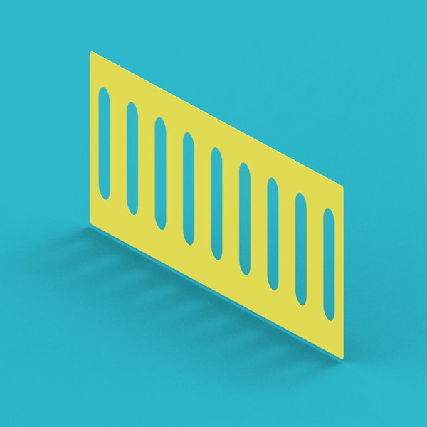 |
| 06 | Cell Epoxy Board | 20 pcs/N |  |
| 07 | Clamping Bar Epoxy Board | 2 pcs/N |  |
| 08 | Cell Busbar | 17 pcs/N |  |
| 09 | Main Terminal Lug | 2 pcs/N |  |
| 10 | Positive Copper Busbar | 1 pc/N |  |
| 11 | Negative Copper Busbar | 1 pc/N |  |
| 12 | Enclosure Cover | 1 pc/N |  |
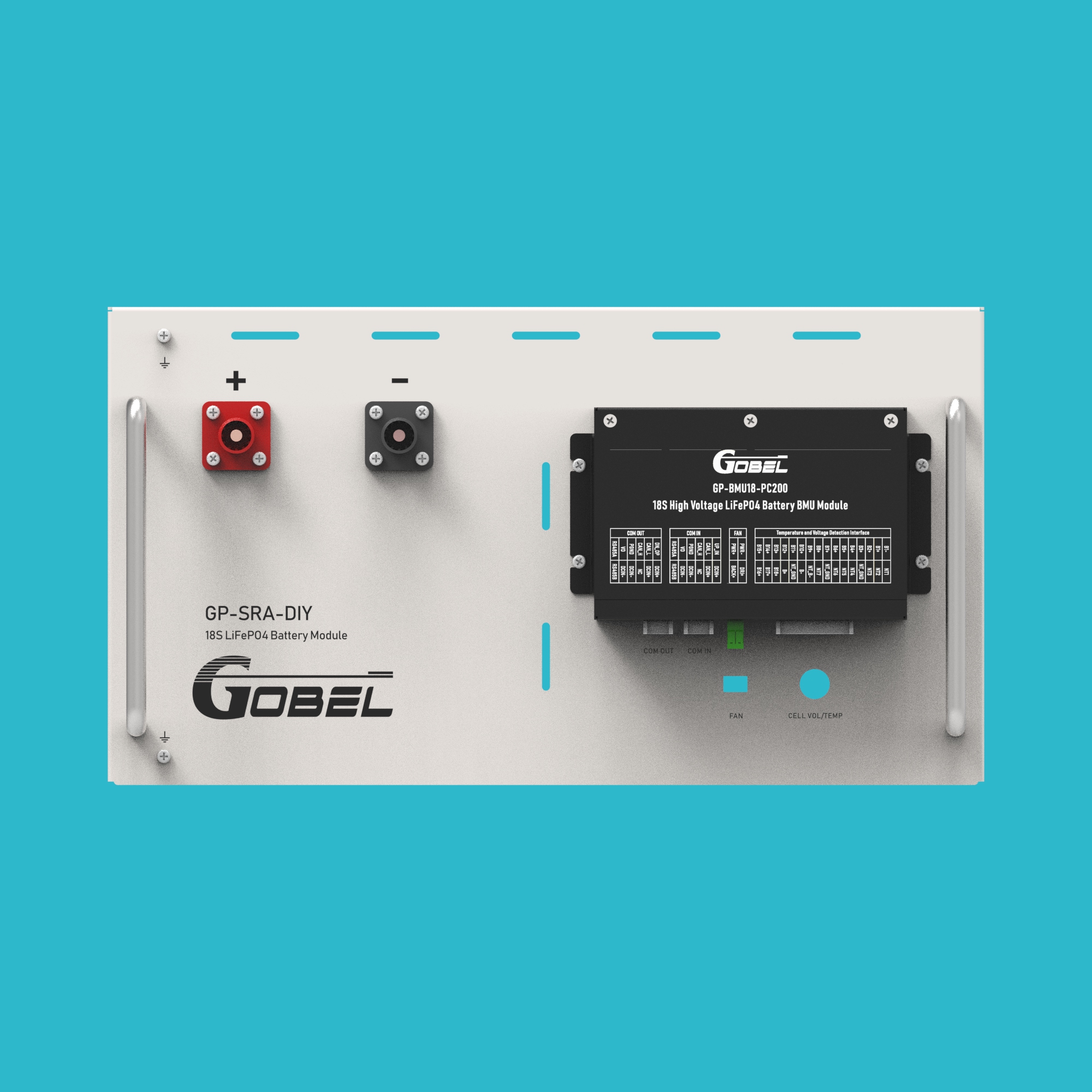
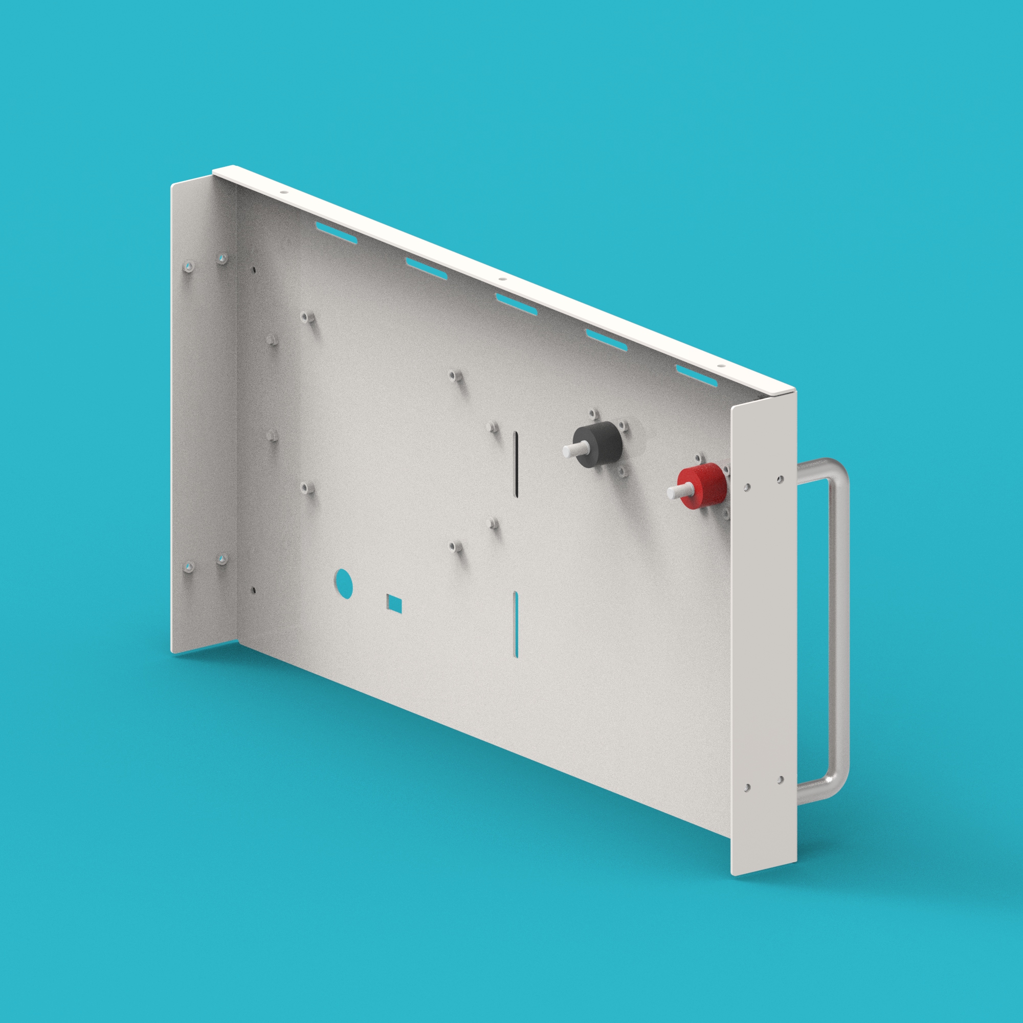
| 13 | Enclosure Panel | 1 pc/N | 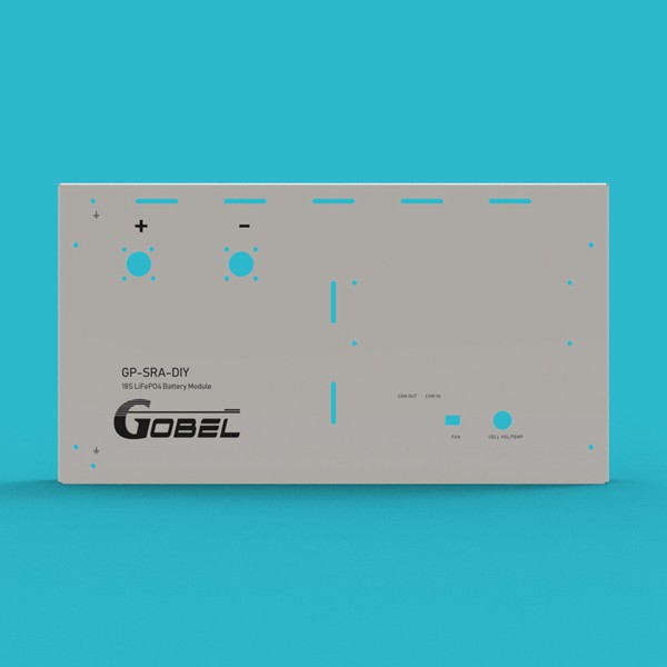 |
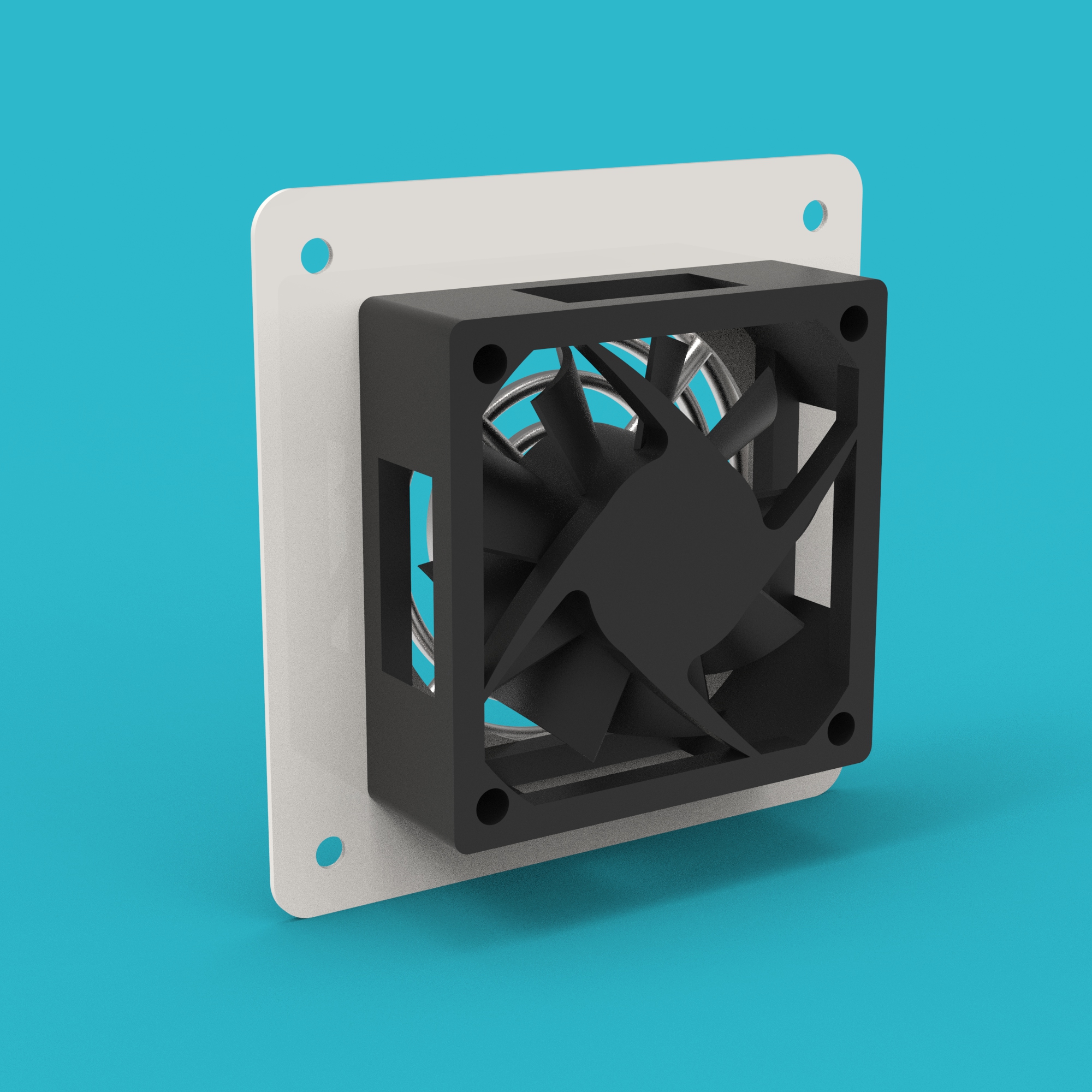
| 14 | Fan | 2 pcs/N | 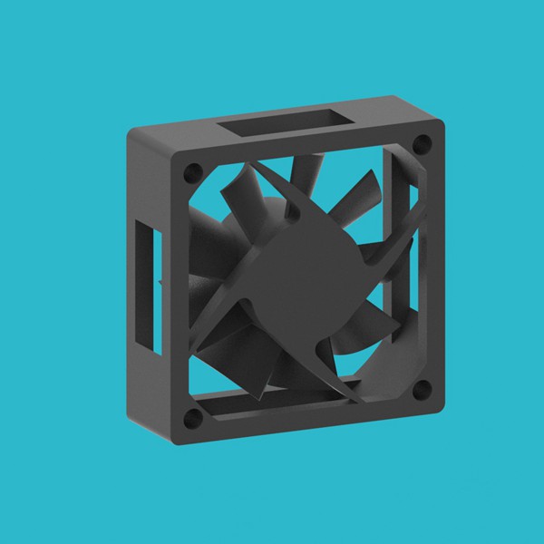 |
| 15 | Fan Fixing Plate | 2 pcs/N |  |
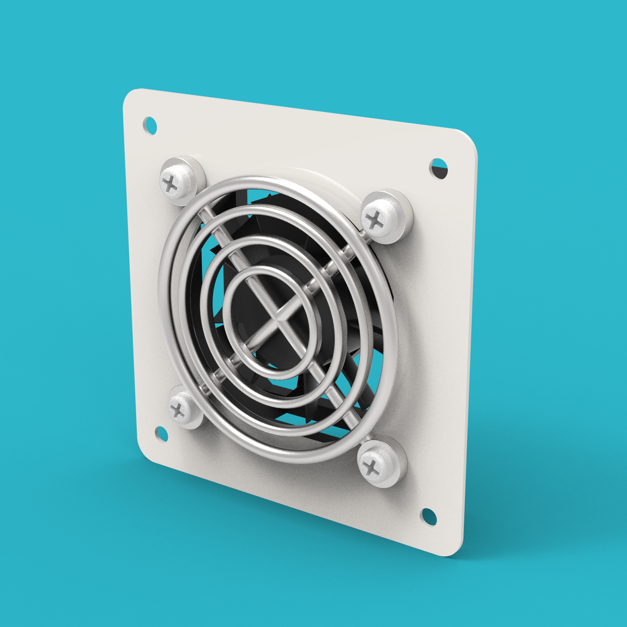
| 16 | Fan Guard | 2 pcs/N |  |
| 17 | BMU | 1 pc/N | 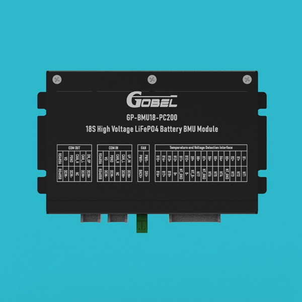 |
| 18 | High-Voltage Box | 1 pc (System) | 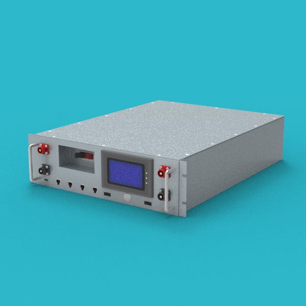 |
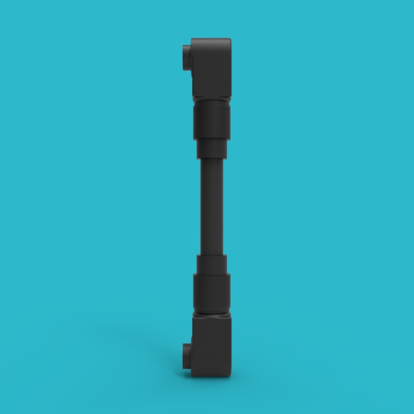
| 19 | BMU Communication Cable | 1 pc/N | 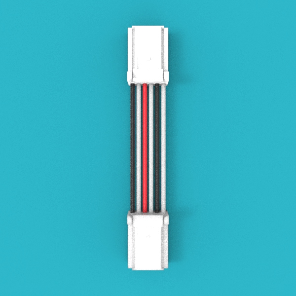 |
| 20 | Fan Connection Cable | 1 pc/N |  |
| 21 | HV Box to BMU Comm Cable | 1 pc (System) | 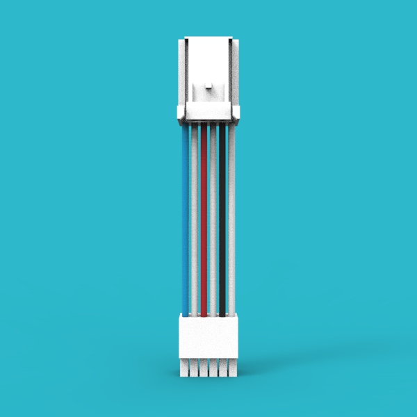 |
| 22 | PC Communication Cable | 1 pc (System) | 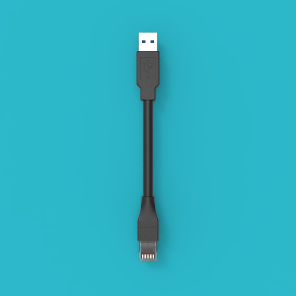 |
| 23 | Positive Terminal Base | 1 pc/N | 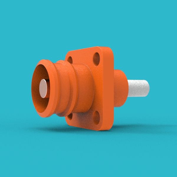 |
| 24 | Negative Terminal Base | 1 pc/N | 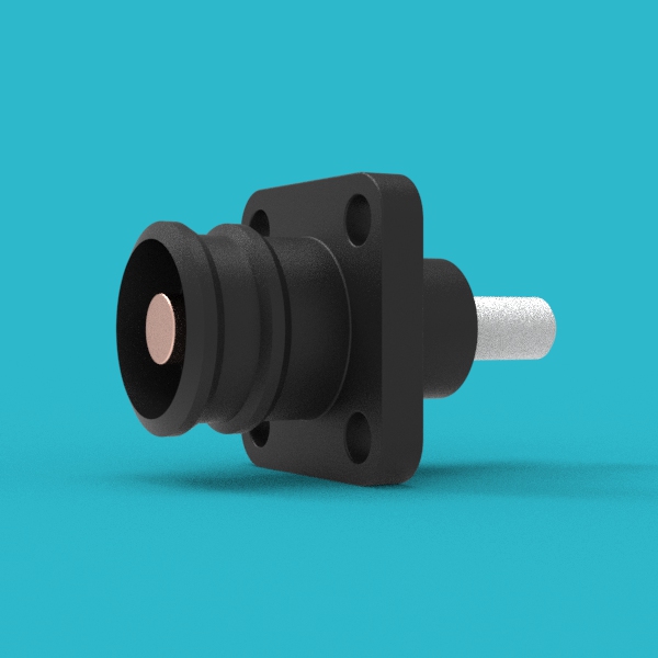 |
| 25 | Positive Terminal Plug | (1 pc +2)/N |  |
| 26 | Negative Terminal Plug | (1 pc +2)/N | 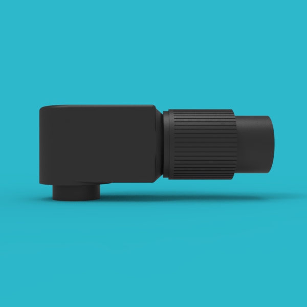 |
| 27 | Handle | 2 pcs/N |  |
| 28 | Case Mounting Ear | 2 pcs/N |  |
| 29 | Voltage Sensing Harness | 1 pc/N |  |
| 30 | Inverter Comm Cable | 1 pc (System) | 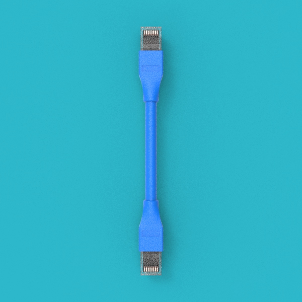 |
Tools and Materials Preparation
The following tools and materials are not included with the product and must be prepared by the user.
| Tool/Material | Specification/Requirement | Purpose |
|---|---|---|
| Insulated Screwdriver Set | Includes common specifications | Tightening screws |
| Torque Wrench | M6/M8/M10 sockets | Tighten screws according to torque requirements |
| Cable Crimping Tool | Suitable for 300A terminals | Crimping positive and negative terminal plugs |
| Multimeter | Insulation level meets high-voltage requirements | Testing voltage, continuity |
| Insulated Rubber Gloves | High-voltage protection level | Personal safety protection |
| Goggles | Impact resistant | Eye protection |
| Insulated Rubber Boots | High-voltage protection | Personal safety protection |
| Dry Powder Fire Extinguisher or Fire Sand | — | Fire emergency |
| Cable Cutting Tool | Suitable for high-voltage cables | Cutting cables to appropriate length |
| Insulation Tape | High-voltage insulation level | Insulation protection |
Screw Torque Requirements
Be sure to use a torque wrench to tighten the screws according to the following standards. Too loose or too tight may lead to poor connection or component damage.
| Screw Specification | Torque Requirement |
|---|---|
| M6 | 8N·m |
| M8 | 15N·m |
| M10 | 15-20N·m |
Assembly Steps
Fan Assembly Pre-installation
Step 1: Assemble the fan assembly
Assemble the Fan (14), Fan Fixing Plate (15), and Fan Guard (16) together. A total of 2 assemblies are needed for later use.
- Note that the text on the fan label should face towards the fan guard.
- Ensure the fan is installed firmly without looseness.
Enclosure Panel Assembly Pre-installation
Step 2: Assemble the enclosure panel assembly
Assemble the Enclosure Panel (13), Positive Terminal Base (23), Negative Terminal Base (24), BMU (17), and Handles (27) together for later use.
It is recommended to pre-arrange the positions of each component on the workbench to ensure accurate alignment during installation.
Series Cable Pre-installation
Step 3: Assemble inter-pack series cables
Use a cable crimping tool and an appropriate length of cable to crimp the Positive Terminal Plug (25) and Negative Terminal Plug (26) to form inter-pack series cables.
- Ensure the crimp is firm and not loose.
- The cable length should be determined based on the actual spacing between battery packs.

Step 4: Assemble battery pack to HV box positive connection cable
Use a cable crimping tool and an appropriate length of cable to crimp two Positive Terminal Plugs (25) to form a battery pack to HV box positive connection cable.

Step 5: Assemble battery pack to HV box negative connection cable
Use a cable crimping tool and an appropriate length of cable to crimp two Negative Terminal Plugs (26) to form a battery pack to HV box negative connection cable.
Main Battery Pack Assembly
Step 6: Install fan assembly into the enclosure
Install the fan assembly onto the Enclosure Case (01). The fan wires should pass through the holes on the enclosure frame.
- Ensure the fan label faces outwards.
- Fan wires should pass through the reserved holes in the enclosure frame to avoid pinching.
Step 7: Install bottom and side epoxy boards
Place the Bottom Epoxy Boards (04) and Side Epoxy Boards (05) into the enclosure.
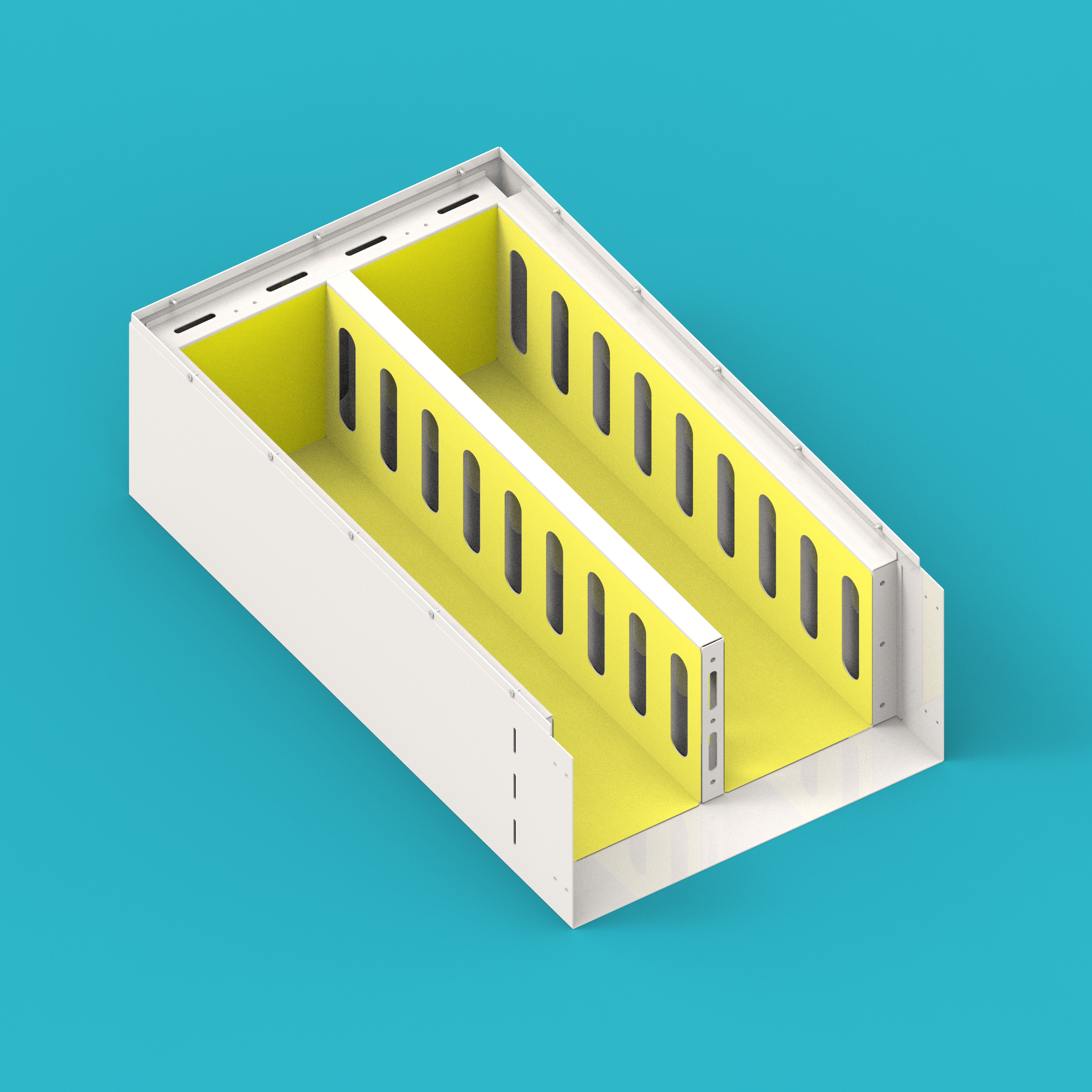
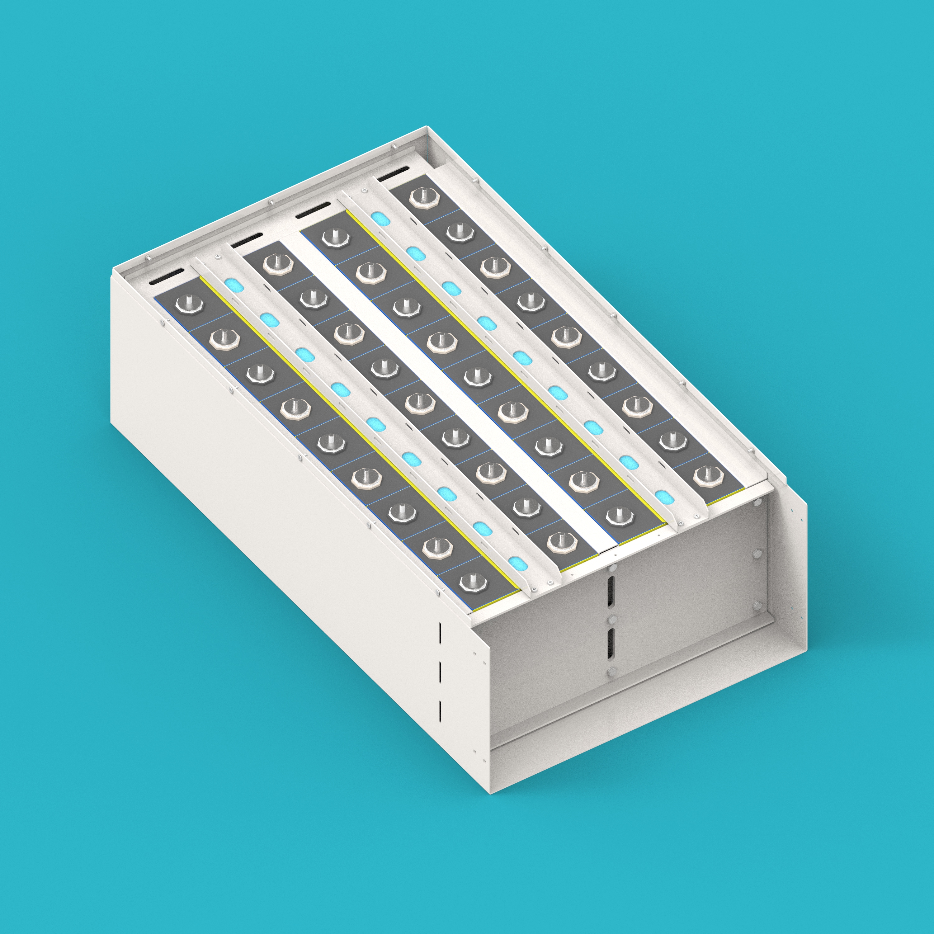
Step 8: Install cells into the enclosure
Place the cells into the Enclosure Case (01), paying attention to the positive and negative directions of the cells.
The positive and negative directions of the cells must be correct, otherwise it will lead to subsequent connection errors.
Step 9: Install cell compression plate
Install the Cell Compression Plate (02) at the end of the cells to prevent cell expansion.
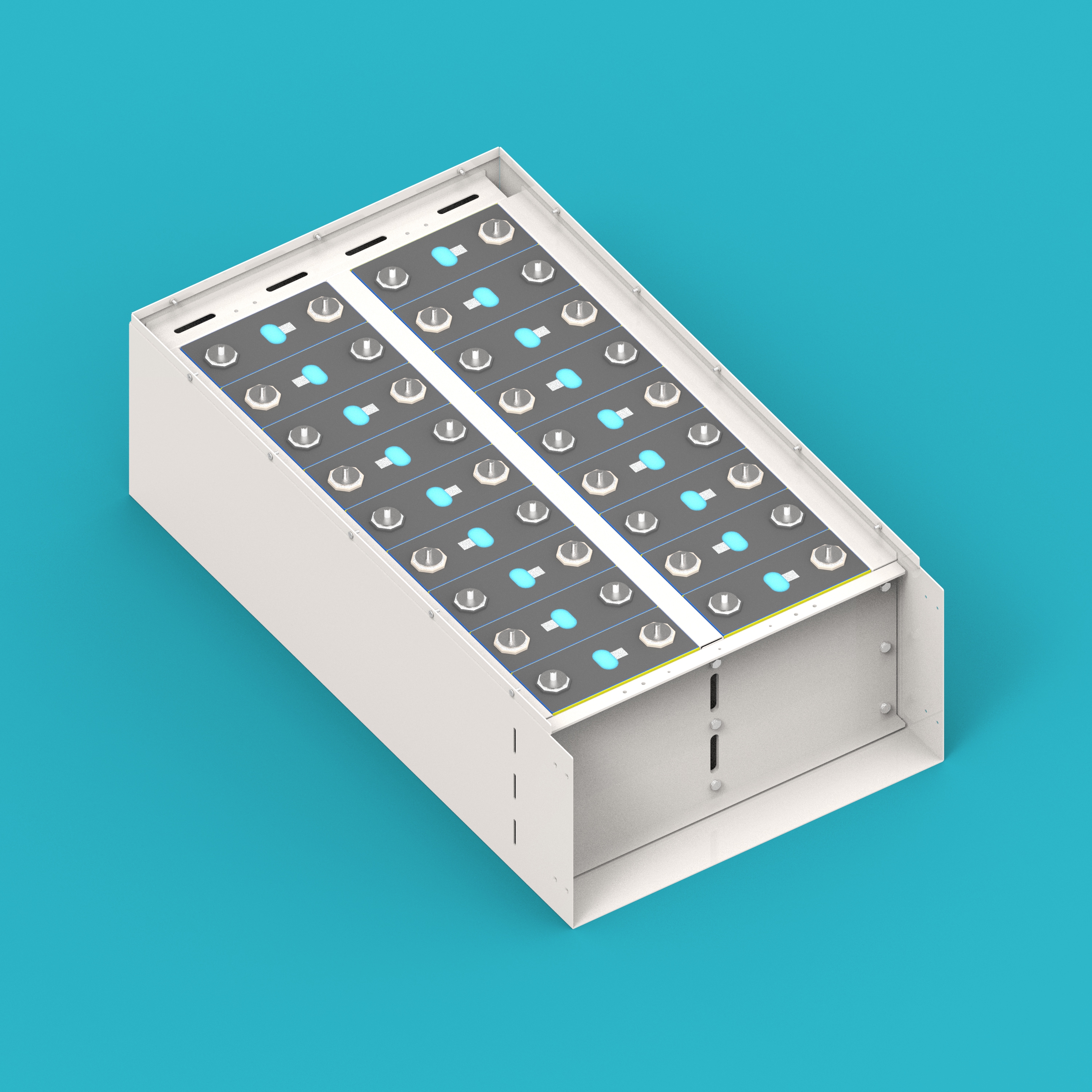
Step 10: Install clamping bar epoxy board
Install the Clamping Bar Epoxy Board (07) above the cells.
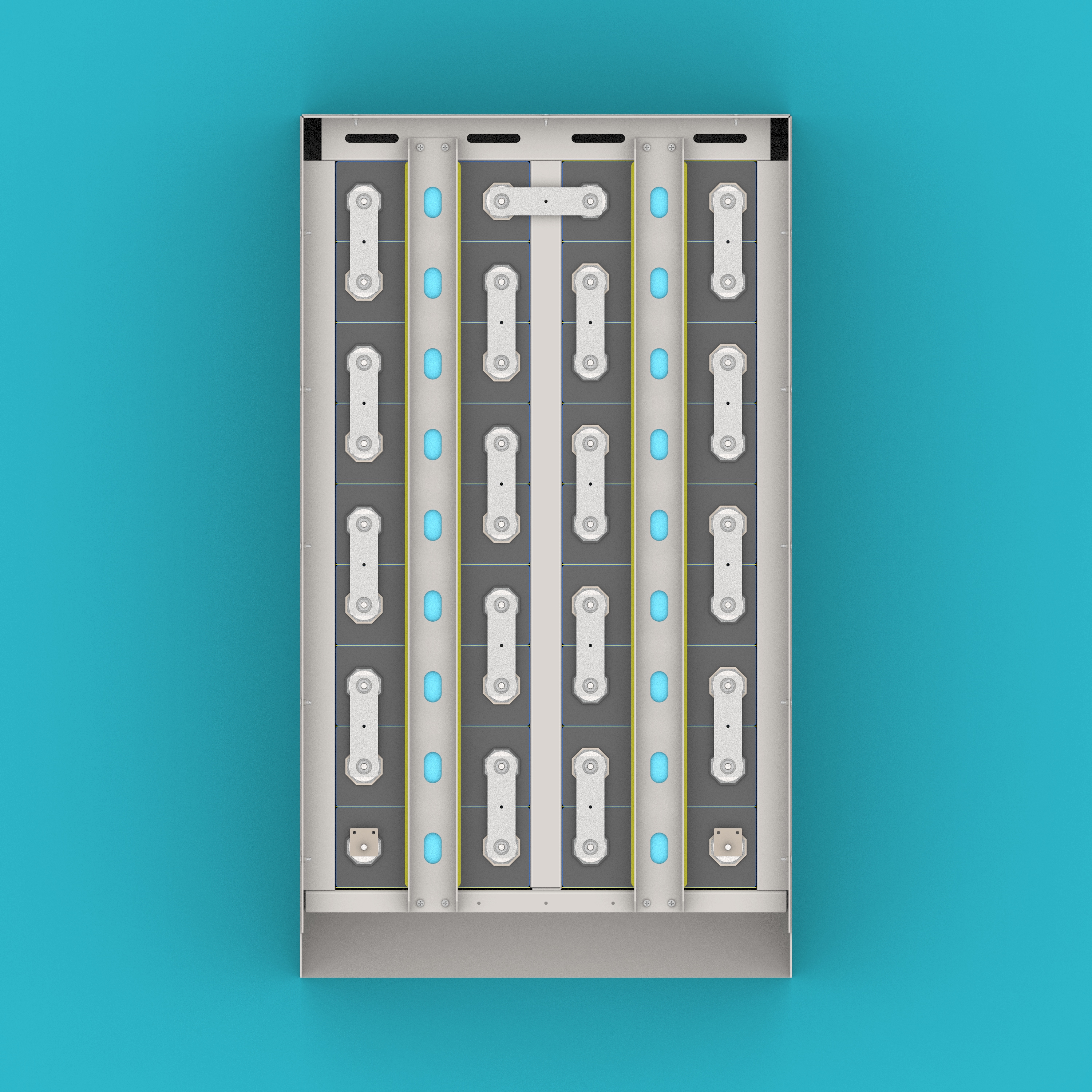
Step 11: Install cell clamping bar
Install the Cell Clamping Bar (03) above the clamping bar epoxy board.
Electrical Connections
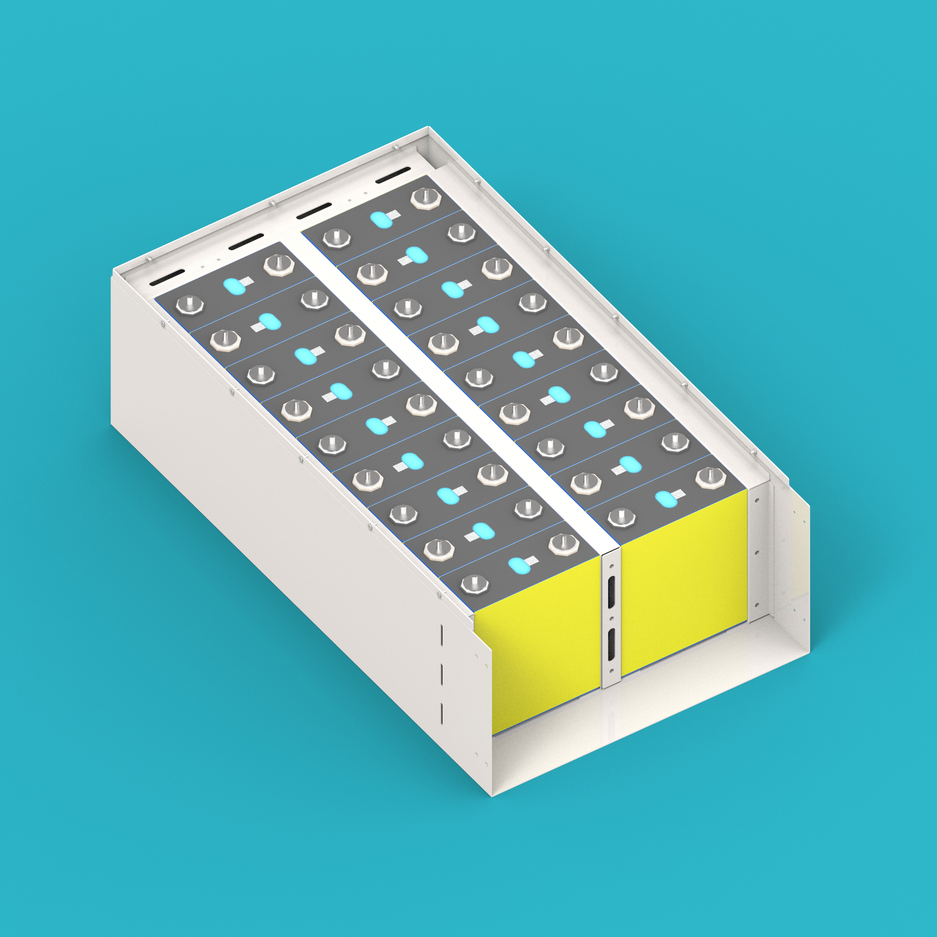
Step 12: Install cell busbars and main terminal lugs
Install the Cell Busbars (08) and Main Terminal Lugs (09).
- This step involves high-voltage connections. Please ensure insulation protection is in place before operation.
- Busbars should be installed firmly, and contact surfaces should be tight.
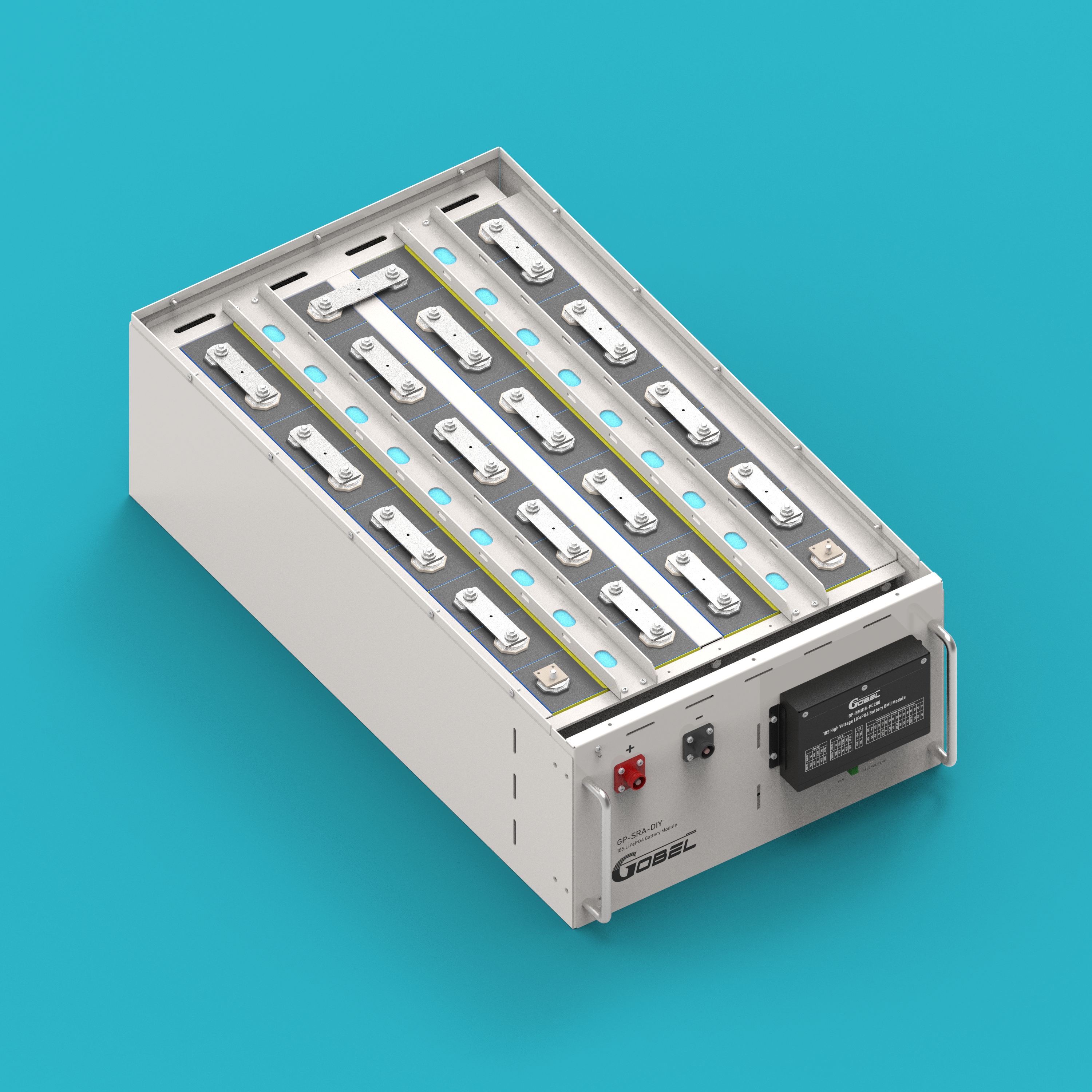
Step 13: Install enclosure panel assembly
Install the assembled enclosure panel assembly onto the case. Before installation, thread the Voltage Sensing Harness (29) and Fan Connection Cable (20) through the panel holes.
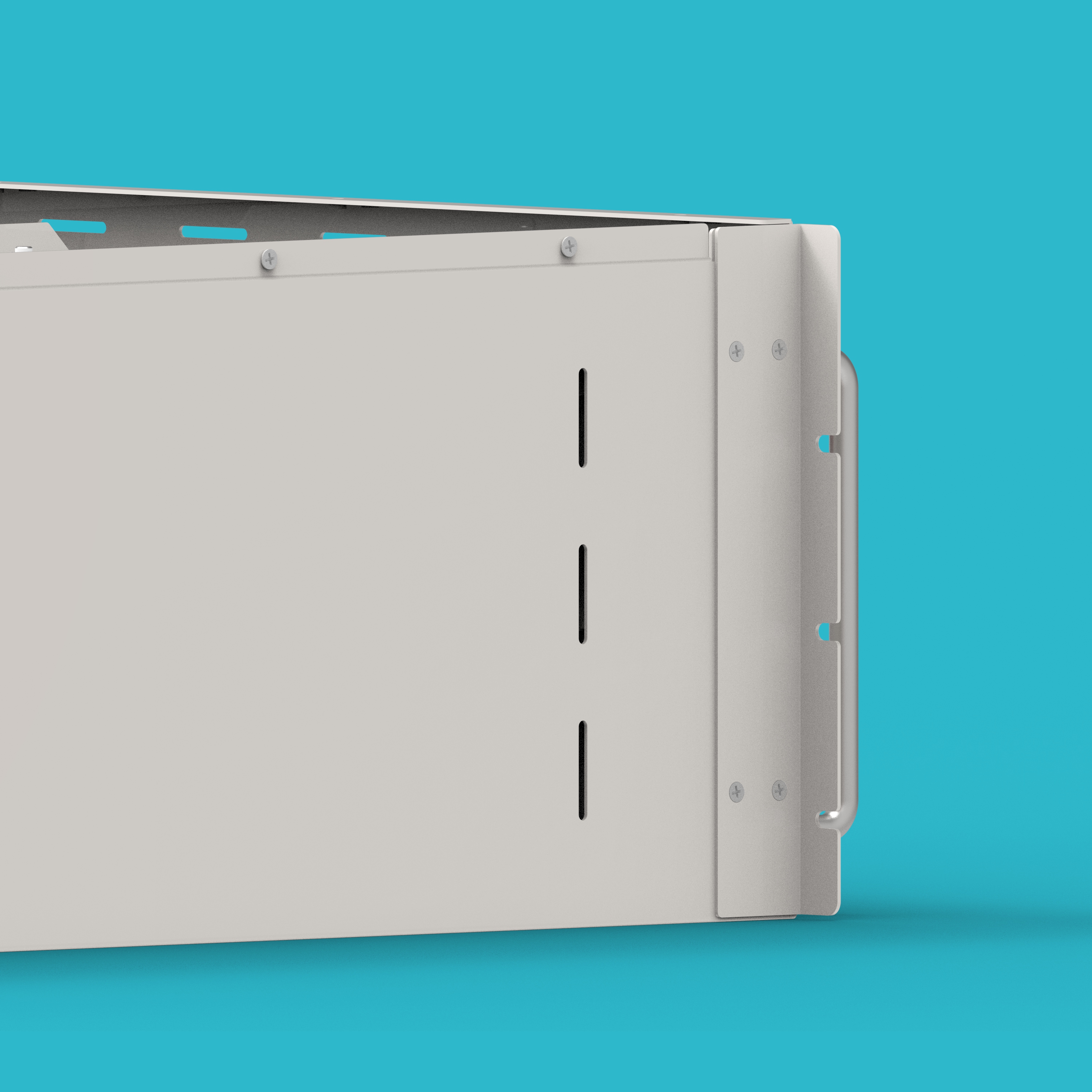
Step 14: Install case mounting ears
Install the Case Mounting Ears (28) onto the enclosure.
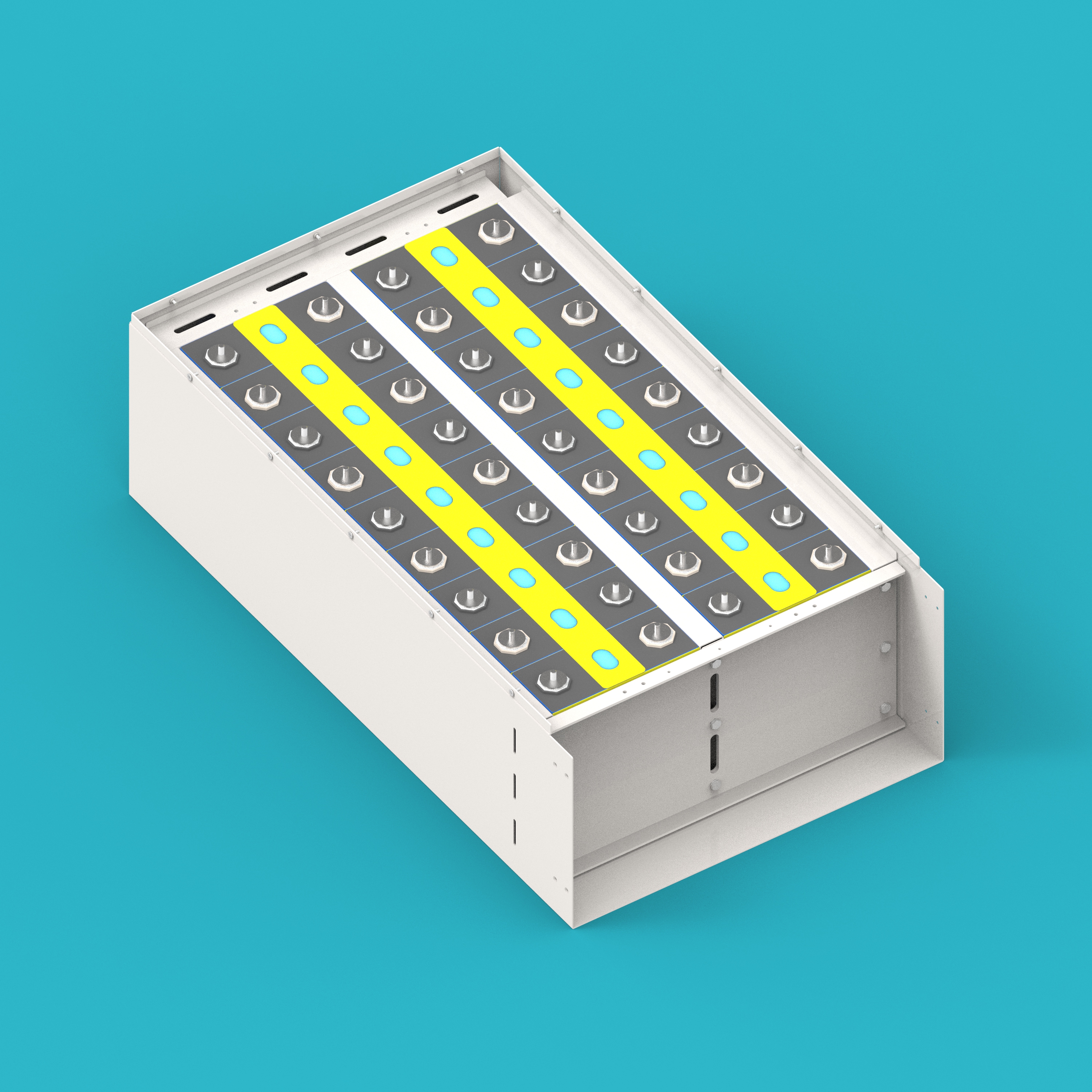
Step 15: Connect voltage sensing harness and fan connection cable
- Connect the Voltage Sensing Harness (29) to the corresponding cells.
- Connect the Fan Connection Cable (20) to the fan lead wires.
- Connect the other end of the voltage sensing harness to the CELL VOLT/TEMP port on the BMU.
- Connect the other end of the fan connection cable to the FAN port on the BMU.
- Ensure the voltage sensing harness is connected to each cell in order.
- Pay attention to the positive and negative correspondence for the fan connection cable.
Step 16: Install positive and negative copper busbars
Install the Positive Copper Busbar (10) and Negative Copper Busbar (11).
- Copper busbar connections must be tight. Use a torque wrench to tighten to the standard torque.
- Ensure the copper busbars maintain a safe distance from other metal parts.
Final Assembly Completion
Step 17: Install enclosure cover
Install the Enclosure Cover (12) onto the enclosure.
- Check that no tools or debris are left inside the enclosure before installation.
- Ensure the cover is well-sealed.
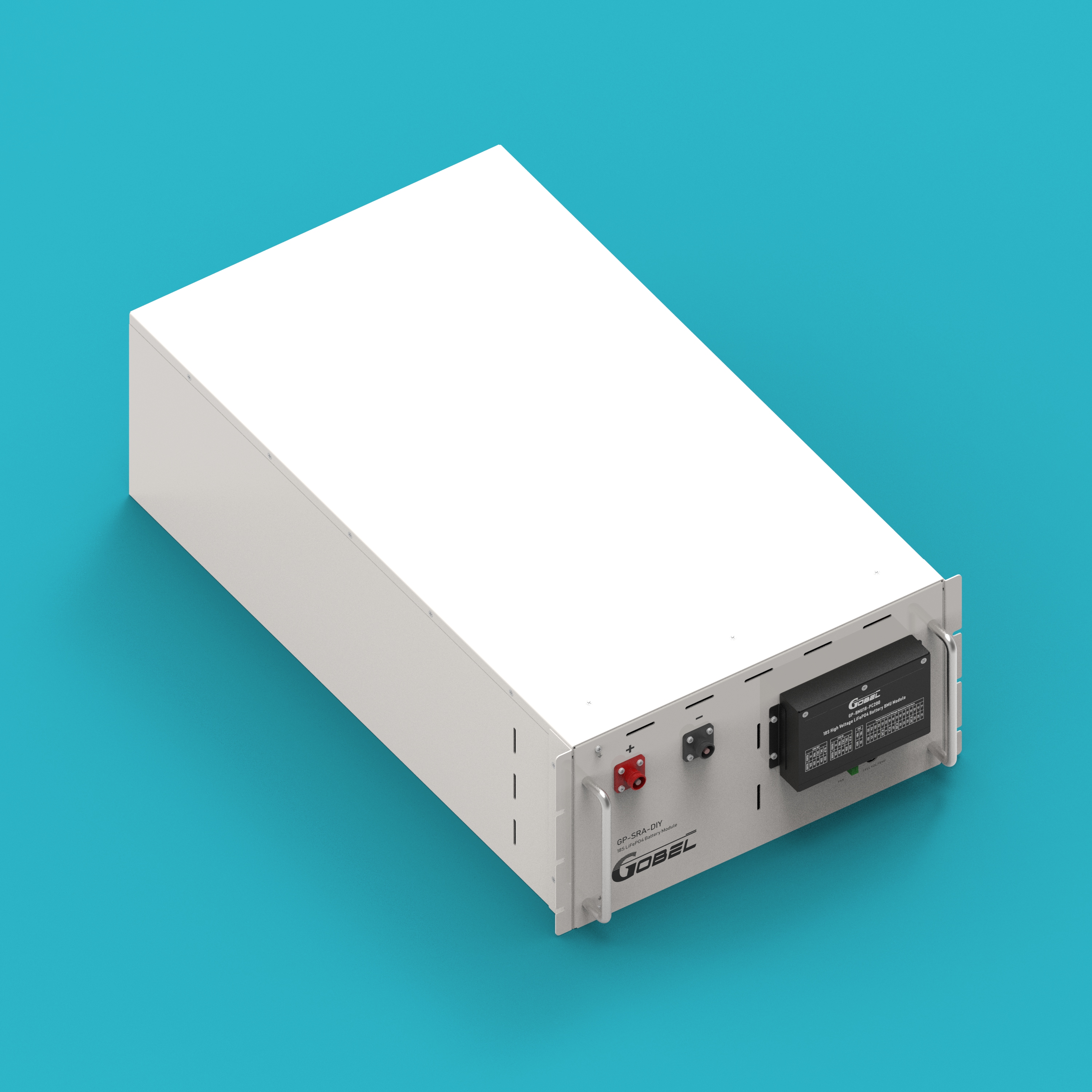
Step 18: Battery pack assembly complete
Battery pack assembly is finished. Check all connections for firmness and confirm no steps were missed before proceeding to the next step of system connection.
- Check if all screws are tightened according to torque requirements.
- Check if all electrical connections are correct and firm.
- Check that no metal debris is left inside the enclosure.
- Check if the fans rotate normally.
Connection Steps
The following connection steps are used to connect multiple battery packs with the high-voltage box to form a complete high-voltage system. The system requires at least 5 battery packs and a maximum of 15 battery packs connected in series.
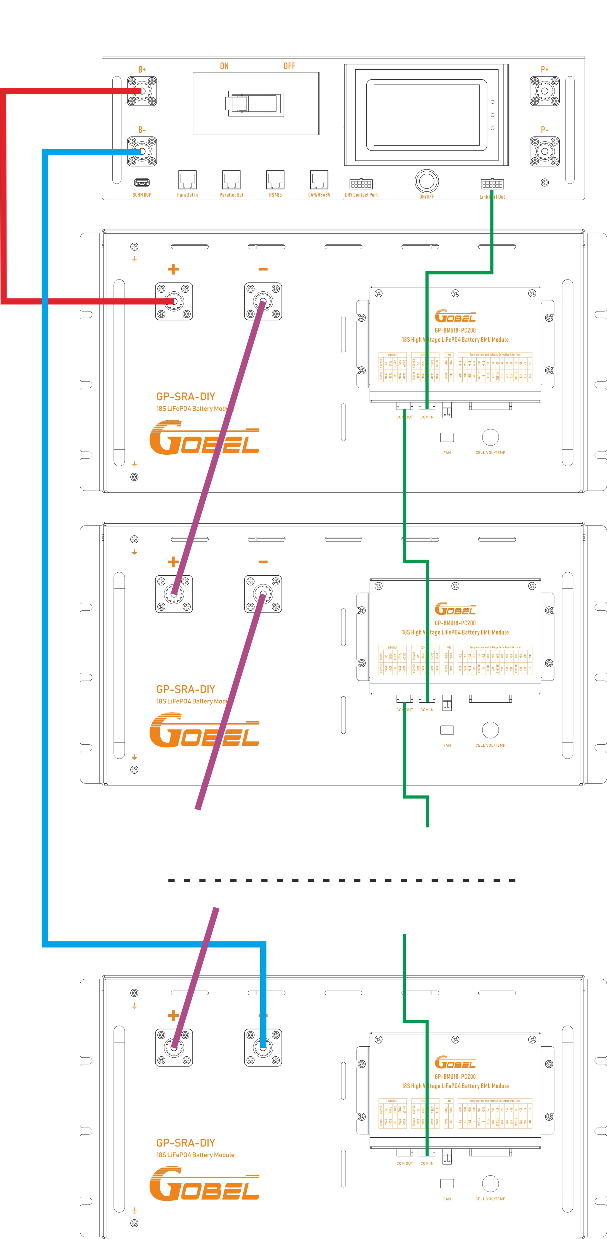
Step 1: Inter-pack series connection
Connect the positive pole of the first battery pack with the negative pole of the second battery pack using an inter-pack series cable. Continue this process to connect all battery packs in series.
Step 2: Communication connection between HV box and the first battery pack BMU
Connect the Link Port Out of the HV box with the COM IN port of the first battery pack using the HV Box to BMU Comm Cable (21).
Step 3: BMU communication connection between battery packs
Connect the COM OUT port of the first battery pack with the COM IN port of the second battery pack using the BMU Communication Cable (19). Continue this process to connect all BMU communication ports in series.
Step 4: Positive connection between HV box and the first battery pack
Connect the B+ port of the HV box with the positive pole of the first battery pack using the battery pack to HV box positive connection cable.
Step 5: Negative connection between HV box and the last battery pack
Connect the negative pole of the last battery pack with the negative pole of the HV box using the battery pack to HV box negative connection cable.
- Ensure all circuit breakers are in the disconnected state before connecting.
- Check all wiring for correctness and firmness after connection is complete.
- Use a multimeter to check if the total voltage is normal before powering on for the first time.
Port Diagram
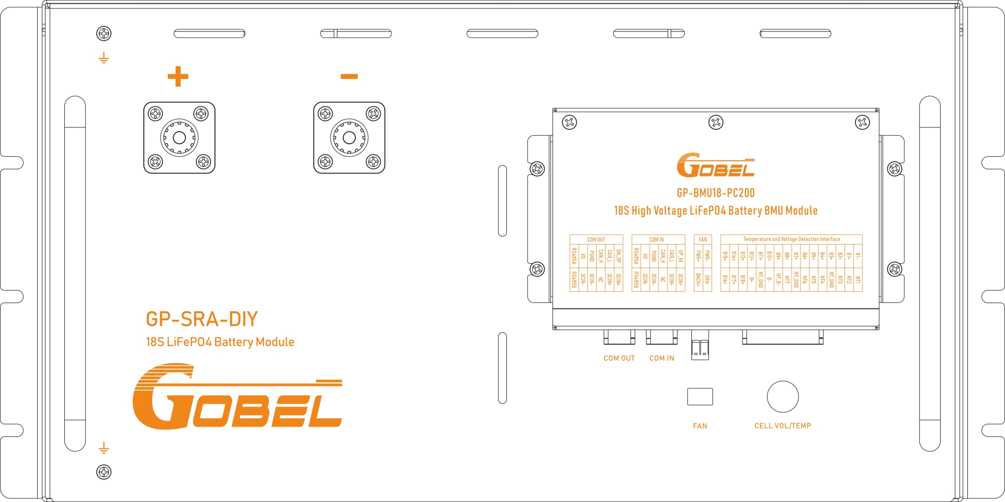
Battery Pack Port Diagram
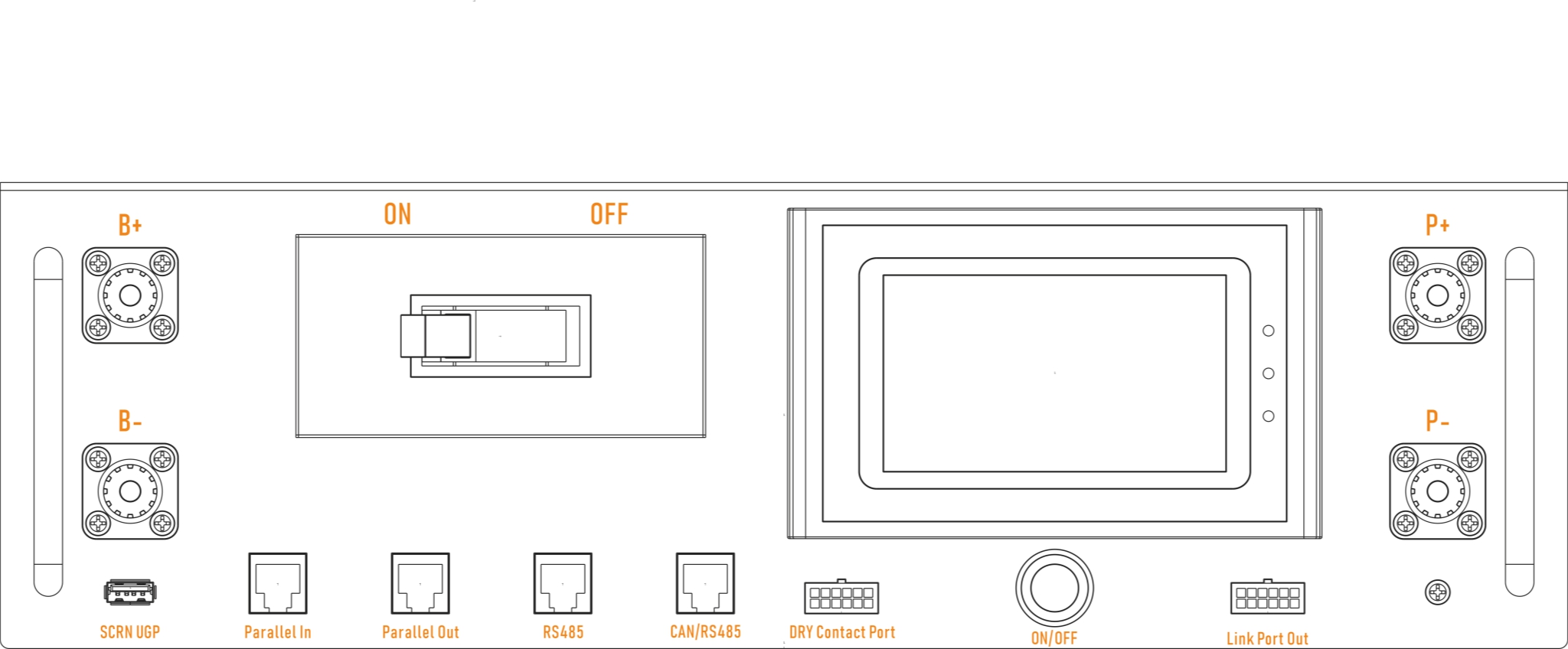
High-Voltage Box Port Diagram
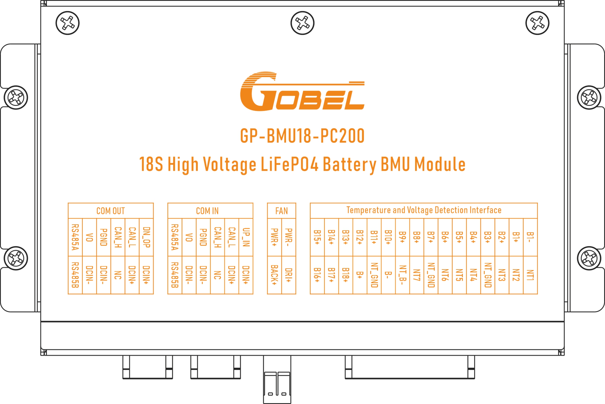
BMU Port Diagram
Contact Information
In case of troubleshooting issues that cannot be resolved, please contact Gobel Power technical support:
- Official Website: www.gobelpower.com
- Technical Support Email: [email protected]